Continue to Site

Eng-Tips is the largest engineering community on the Internet

Intelligent Work Forums for Engineering Professionals

  • Congratulations SDETERS on being selected by the Eng-Tips community for having the most helpful posts in the forums last week. Way to Go!

2 Datums from the same features. 2

Status
Not open for further replies.

Rwelch9

Mechanical
Apr 22, 2020
116
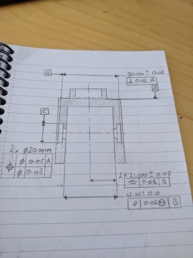
straightness_imjio1.jpg


Hi,

Can you have two Datum from the same Datum features.

See my drawing attached.

Datum C if from two cylindrical pockets axis and Datum B is the mid plane from the two bottom faces of the pockets .

Datum B and Datum C are from the same two features , is this okay ??

Also how / can you have a perpendicular call from each face that make up Datum B to Datum A ?

In my drawing the perpendicular call out is from the mid plane Datum B to Datum A .

However i feel it is best to check theses faces individually to A ??

Thanks

Ross
 
Replies continue below

Recommended for you

Datum C if from two cylindrical pockets axis and Datum B is the mid plane from the two bottom faces of the pockets .

Datum B and Datum C are from the same two features , is this okay ??

Yes, it is okay. GD&T grammar is good.


Also how / can you have a perpendicular call from each face that make up Datum B to Datum A ?

Where do you see this?

In my drawing the perpendicular call out is from the mid plane Datum B to Datum A .

yes, you are correct.

However i feel it is best to check theses faces individually to A ??
Sorry to say, but your personal feelings do not have any input in the way you have to qualify your parts per the drawing requirements
If you do check the individual faces to datum A, then you might accept some parts that are not per the drawing requirements, unless you prove otherwise (you might be able to do some math, come up with some new tolerances on the individual faces to A and then prove that what you accept per your new calculations are ALSO meet the print requirements)


Datum C if from two cylindrical pockets axis and Datum B is the mid plane from the two bottom faces of the pockets .

If you want C to be the datum feature formed by BOTH pockets, I would personally attach the datum feature symbol to the FCF if possible. As it is it seems to me ambiguous whether you want it to apply to the pair of holes or just the one on the right which the dimension is attached to. Perhaps not everyone would take it that way but I wouldn't leave the option open.

Side note - you have only orientation controls on C. There is no requirement that the two pockets are coaxial without a tolerance of location applied (ie: position).

Datum B and Datum C are from the same two features , is this okay ??

They sure look like different, unique features to me. The bottom/flat face of a pocket and its cylindrical diameter are different features.

Also how / can you have a perpendicular call from each face that make up Datum B to Datum A ?

In my drawing the perpendicular call out is from the mid plane Datum B to Datum A .

However i feel it is best to check theses faces individually to A ??

Why do you feel its better to check/control them individually? It is more likely that control of perpendicularity of the width shaped feature (center plane) better represents function since taking an educated guess based on the general form of your part it is likely a single component mates to the inside of this width and the faces function together instead of each face individually, and it allows use of the MMC modifier if desired.*

That said
you surely CAN apply individual perpendicularity callouts, if you as the designer deem it best satisfies your requirements. Simply apply a perpendicularity FCF to each face instead of the width - simple as that.

*Edit - for some reason I was thinking C was an inside width. I see why you might want to control them separately, and I see no issue with it.
 
greenimi,

Thanks for the reply.


Quote:
Also how / can you have a perpendicular call from each face that make up Datum B to Datum A ?

Where do you see this?


To answer you question above , it is not on the drawing , i was wondering if it could be added in ? for example the two planes that make up datum Feature B could they be checked individually to Datum A.

Checking the mid plane is perpendicular to A always gives a good reading . However checking them individually they can be slightly out .

My thinking is if there individually perpendicular to Datum A then the mid plane cannot be wrong ?
 
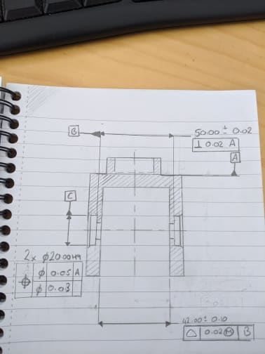
IMG_20200430_130847_gpd5wq.jpg


thanks everyone for the help its much appreciated.

I have tried to re dimension the part below .

Would anyone have any objections to these call outs ?

or add anything in ?
 
Rwelch9,

-Same comment as my 30 Apr 20 12:40 on the placement of datum feature symbol C.
-What feature is B supposed to be? The pair of edges as the intersection of the chamfers and cylindrical pockets? This is not a FOS and would be a poor datum feature. Previously it was the bottom faces of the pockets, why the change?
-The symmetry specification is not valid, it would need to be applied to the width, not just one side. Personally I would avoid symmetry, it was actually removed from the 2018 version. Position might be the better control, or even profile.
 
drawing_rev2_pgmgvs.jpg


Chez311,

You are 100% correct, Datum B is from the two bottom faces of the pockets.

i retract my statement about them being the same Feature as you pointed out makes total sense they are a cylindrical diameter and the other is a flat face.

Regarding my updated drawing .

I am not sure what you mean by placing the Datum C symbol to the feature control frame ?

Again i am new to this and still learning , so all your help is appreciated.

Thanks

Ross
 
I see you've added a profile control. Profile is a surface control and must be applied to the surface(s) of a feature(s), not the width/center plane.

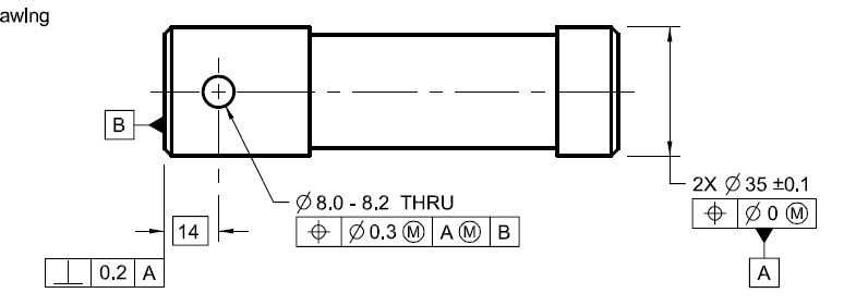
In regards to the datum feature placement, I mean like the below datum feature A attached to the FCF for position.

I assume from your previous posts you are drawing to ASME, though I'm not sure what version. Do you have access to the Y14.5 standard to which your drawings are compliant? It can be purchased from the ASME site, and judging by your questions it will benefit you to review the primary document to gain a deeper understanding than we can provide here answering individual questions. There are also a plethora of learning services and books for both ASME and ISO which may be worth looking at as well.

coaxial_mf1dhe.jpg
 
Regarding profile control would i have an arrow at both faces calling out surface of a profile to Datum A and B ?

Instead of Profile could i Just use position instead ?


What is the difference from having it placed there or they way i had it in my drawing ?


I am receiving the Complete ASME Y 14.5 book tonight . So yes it is definitely something i need to familiarise myself with.
 
You can certainly utilize position instead.

What is the difference from having it placed there or they way i had it in my drawing ?

I assume you mean the datum feature symbol. Theres not a significant difference - personally I just believe that if if you only apply it to the single width dimension it may be unclear to some whether it applies to only the single pocket which has the dimension attached or the pattern of 2X pockets. Applying it to the FCF eliminates this ambiguity - your GD&T should be as clear as possible and eliminate (or in reality - reduce) the possibility of multiple interpretations.
 
I was always under the impression that positional tolerance did not work with planes.


does positional act the same as parallelism in this case except it will also control the location not only just if there parallelism ?

 
According to ASME position tolerance may not be applied to a single planar feature, it must be on a Feature of Size (FOS). You have a width dimension which is a FOS and therefore may have a position tolerance applied to the width. A position tolerance cannot be directed at each individual surface, that would be invalid.

does positional act the same as parallelism in this case except it will also control the location not only just if there parallelism ?

Position controls location and orientation. Parallelism controls only orientation.
 
Status
Not open for further replies.

Part and Inventory Search

Sponsor