Daewoo200
Mechanical
- Apr 15, 2022
- 4
I have two separate questions. They are the following:
1. I am confused about how a datum axis is established on a CMM. Is the axis established wherever the hole ends up being -whether the hole is in position tolerance or out of position tolerance? Or is the axis established based off of the basic dimensions and the axis is perfectly positioned? If the axis is always perfectly positioned based off of the basic dimensions, this means that the hole will never be perfectly coaxial/concentric with the axis since there will always be some inherent error in the position of the hole. Can you help clarify this for me?
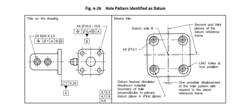
2. Myself and a coworker are curious about using a hole pattern as a datum. I say that it can be done (I showed him my textbook and that it does satisfy our design intent), but he says that he doesn't understand what a hole pattern datum actually is so he doesn't want to use it. Now I am curious - how should an inspector interpret a hole pattern that is called out as a datum?
Say for example that the hole pattern is called out as datum E. Is there a datum axis E that goes through each hole in the pattern? Or does a single axis go through the middle of the entire pattern? What if some holes are not straight/true to one another within the pattern?
I also want to treat the holes in the pattern as RFS. Will a hole pattern datum still work at RFS?
For other features that are referencing a hole pattern datum in a FCF, I feel like it would be hard for them to pass inspection since that feature would have to be gaged to that entire pattern. Is this correct?
Help clearing up my confusion for my two questions is greatly appreciated.
Thanks,
Chris
1. I am confused about how a datum axis is established on a CMM. Is the axis established wherever the hole ends up being -whether the hole is in position tolerance or out of position tolerance? Or is the axis established based off of the basic dimensions and the axis is perfectly positioned? If the axis is always perfectly positioned based off of the basic dimensions, this means that the hole will never be perfectly coaxial/concentric with the axis since there will always be some inherent error in the position of the hole. Can you help clarify this for me?
2. Myself and a coworker are curious about using a hole pattern as a datum. I say that it can be done (I showed him my textbook and that it does satisfy our design intent), but he says that he doesn't understand what a hole pattern datum actually is so he doesn't want to use it. Now I am curious - how should an inspector interpret a hole pattern that is called out as a datum?
Say for example that the hole pattern is called out as datum E. Is there a datum axis E that goes through each hole in the pattern? Or does a single axis go through the middle of the entire pattern? What if some holes are not straight/true to one another within the pattern?
I also want to treat the holes in the pattern as RFS. Will a hole pattern datum still work at RFS?
For other features that are referencing a hole pattern datum in a FCF, I feel like it would be hard for them to pass inspection since that feature would have to be gaged to that entire pattern. Is this correct?
Help clearing up my confusion for my two questions is greatly appreciated.
Thanks,
Chris