Continue to Site

Eng-Tips is the largest engineering community on the Internet

Intelligent Work Forums for Engineering Professionals

  • Congratulations KootK on being selected by the Eng-Tips community for having the most helpful posts in the forums last week. Way to Go!

20.0mm H7 Tolerance with GD&T Circularity 3

Status
Not open for further replies.

engineeringspread

Mechanical
Mar 14, 2020
13
Hello All,

New to the forum and would just like some other opinion on this subject. I have specified a hole tolerance to accept a bearing, which is a 20.0 H7 +0 / +0.021 the centre position is defined by GD&T position and datum references, the hole depth is around 20mm. The selected manufacturer is asking for a circularity tolerance which confuses me somewhat as in my opinion the H7 tolerance accommodates this as it is a relatively tight tolerance and doesn't really allow for any significant circularity runout.....if I were to add circularity a tolerance of 0.01 would be required to have any effect due to the H7 tolerance.

Interested to know others opinions on this situation.

Thanks - James
 
Replies continue below

Recommended for you

I have one additional follow up question (in top of the previous one related to circularity)

If the drawing states :
"20.0 H7 +0 / +0.021" for size and ISO 2768-mK
(no ISO 2768-mK-E and no ISO286-2)
then how do we know if envelope requirement is default or not?

What are the factors that tell us the envelope requirement is enforced?

 
Kedu said:
Would be a difference between calling out ISO 2768-mK-E and the original indicated standard ( ISO2768-mK)?
I personally don't see any.

If there is, which one?

When it comes to the allowable amount of circularity tolerance, I don't see any difference too. In both cases the maximum allowable circularity error is 0.021 because this is what ISO 2768-2:1989 explicitly says in para. 5.1.2 (see my previous post).

There is, however, a significant difference when it comes to the size of the worst-case envelope that the feature cannot violate.

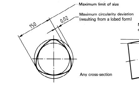
In the 'ISO 2768-mK' case, that size is not determinable. Although one can find the extreme sizes of the enveloping circles in individual 2D cross-sections according to the illustration below (caution: the illustration is for a shaft, not for a hole)...

capture_1111_phnzp9.jpg


... the size of the enveloping 3D cylinder is still not determinable.

In the 'ISO 2768-mK-E' case, the size of the of the enveloping 3D cylinder simply equals to MMS (Maximum Material Size), which is 20.


greenimi said:
"a hole tolerance to accept a bearing, which is a 20.0 H7 +0 / +0.021"
If no Envelope requirement, why the "default" circularity cannot be 0.021 and an extra approx. 30%= 0.0273...

[...]

Pmarc,
What I am doing wrong in my thought process? I have a "shortcut", but not sure where?:):)

greenimi,
Does the underlined part of my reply to Kedu answer your question?
 
pmarc,

pmarc said:
Does the underlined part of my reply to Kedu answer your question?

Yes, it does. Thank you very much.
I am just trying to find my way into the ISO world (labyrinth)
 
Pmarc,


Pmarc said:
There is, however, a significant difference when it comes to the size of the worst-case envelope that the feature cannot violate.

In the 'ISO 2768-mK' case, that size is not determinable. Although one can find the extreme sizes of the enveloping circles in individual 2D cross-sections according to the illustration below (caution: the illustration is for a shaft, not for a hole)...
... the size of the enveloping 3D cylinder is still not determinable.

Thank you for your answer.

May I ask, why the size of the worst case envelope ( the inner boundary if this term is correct) is not determinable?
If we take / combine (maybe even add) the general tolerance for straightness per table 1 from ISO 2768-2 meaning 0.1mm (since the OP said the hole is 20mm depth) and
use greenimi's 30% for circularity ( in each individual 2D cross-section)
then why
0.0273+ 0.1 = 0.1273 is not a good approximation for the worst case envelope?

Thank you to clarify this point of my own missunderstanding.


Sometimes I can't see the forest for the trees, so I made a small mistake ---- as I was too focused on the combination of the form errors----

The inner bounday or the worst-case envelope would be:
20mm - (0.0273+ 0.1 = 0.1273) = 19.8727

Is 19.8727 a good approximation for the worst case envelope?


Kedu,
Your question helped me realize that by saying that in the "ISO 2768-mK" case the 3D boundary is not determinable I made a really simple mistake. I just forgot that ISO 2768-2 defines general tolerances for straightness. [hammer] My apologies.

Having said that, I think that for circularity you would just have to use the size tolerance tolerance value, and not the size tolerance value increased by 30%.
 
pmarc,

You have to do this [hammer] to me too. Why?
Because my "30% added circularity" is valid only in the case of no circularity/ roundness requirement.
(and not valid in this case since roundness is imposed by ISO 2768-2-mK)

If no ISO 2768 is shown, (but only size dimension), then the "built-in" roundness control, in the absence of any other form control could be approximated to an extra "30%"

Am I correct now? [bow]
 
Greenimi said:
I have one additional follow up question (in top of the previous one related to circularity)

If the drawing states :
"20.0 H7 +0 / +0.021" for size and ISO 2768-mK
(no ISO 2768-mK-E and no ISO286-2)
then how do we know if envelope requirement is default or not?

What are the factors that tell us the envelope requirement is enforced?

Per pmarc looks like ISO had a very serious configuration management issue


Pmarc,
Do you know if this issue still exist or has been solved in the meantime, with the new revisions of ISO286-1 and ISO286-2?
 
It has been brought to my attention that I made a mistake in one of my previous posts:

When I said 30% extra circularity I meant the following: If a feature is dimensioned for size and location/position to some DRF (with no ISO 2768 invoked), size limits alone provide roundness control equivalent to approx. 30% of the nominal diameter/nominal size value (and not 30% of the size tolerance value as I mistakenly specified in my previous post). So, in the absence of any other form control, there is a “built-in” roundness requirement of 6mm. (20*0.3=6mm)

Disclaimer: this 30% (found in an ISO training material) is a value that is largely disputed and discussed (some GDT’s experts show it at 15% and others at a value way bigger than 30% as debated in this thread:


Therefore, in the OP’s case (which invoked ISO2768-mK) and following kedu's calculation method, I would say that the inner boundary is
20mm - 0.021(size/circularity) -0.1 (straightness) = 19.879mm

This is probably, the GO gage size to check the combo value of 20.0 H7 when ISO2768-mK is invoked (GO gage is suppose to check if it’s no material where not suppose to be material)

Regarding kedu’s latest inquiry about the ISO’s configuration management issue, I prefer to leave that to the ISO’s experts (maybe pmarc could chime in), as I don’t want to make another mistake….

Have a great weekend.
 
Others may have covered this, but if this is a ball or roller bearing the hole roundness and circularity are pretty much independent of size.

A decent bearing catalog's engineering section will make that clear.
 
Status
Not open for further replies.

Part and Inventory Search

Sponsor