Continue to Site

Eng-Tips is the largest engineering community on the Internet

Intelligent Work Forums for Engineering Professionals

  • Congratulations IDS on being selected by the Eng-Tips community for having the most helpful posts in the forums last week. Way to Go!

220V Line to Line Generator 2

Status
Not open for further replies.

jdoyle3

Mechanical
Nov 20, 2015
5
I am in the US and am trying to convert a genset so that it can be used in China (or for Europe, Australia, etc. with voltage adjustments). The genset is originally configured to run at 60 Hz with 4 leads to produce 240/120V. I have already lowered the engine speed to achieve 50 Hz, so the frequency problem is solved. I have adjusted the voltage regulator so that my line to line voltage is 220V (voltage used in China). I will run my two lines and a ground wire out of the generator, and not use the center-tapped neutral terminal.

The generator now operates at 50 Hz and produces 220V across my two lines.

However, my gut tells me that 220V Line to Line can not be used as if it is 220V line to neutral. I know that I would need to use double pole breakers in this case, but I don't know if that offers enough protection. I want it to be safe for any 220V load that would plug into it.

If it is the case that it is not ok to do this, how do other countries use small gensets? Would they use 3 phase generators to make 380/220V to give you the 220V line to neutral? The problem I would have in doing this is that I may only pull from one or two phases, causing imbalance in the generator. And then I would also have to increase the size of the generator because I would only be using 1 or 2 thirds of it.

Any help is greatly appreciated.
 
Replies continue below

Recommended for you

Is this a single phase generator or a three phase generator?
Either may be four leads, but the three phase configuration will develop 208/120. not 240/120.
If your AVR (Automatic Voltage Regulator) has UFRO (Under Frequency Roll Off) you should set it for 50 Hz (Usually jumper selectable).
After setting the UFRO for 50 Hz you should reset the Voltage.
Some 220/380 systems are similar to our 120/208 Volt systems in that the wye point or neutral is grounded. When 220 Volts is supplied in this environment, it is treated similar to a 120 Volt supply in North America in that one line is hot and one line is grounded.
For 220 Volt, 50 Hz single phase, remove the ground from the center tap and insulate it.
I have had a number of single phase sets supplied from the UK, that were converted from 220 Volts, 50 Hz to 120 Volts, 60 Hz. Unfortunately the ground connection was left on one line instead of being reconnected to the center tap or neutral point.
Hopefully someone with local knowledge will post in and confirm that standards in China for one phase of a 220/380 Volts system are the same as in the UK.

Bill
--------------------
"Why not the best?"
Jimmy Carter
 
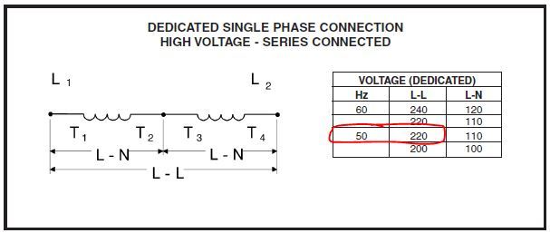
Thanks for the reply. It is a single-phase 4 lead generator. And yes, we changed the jumper on the regulator to 50 Hz. Here is the schematic:
Gen_jgnxjf.jpg
 
T1 Hot L1
T2-T3 Insulate
T4 ground L2

Bill
--------------------
"Why not the best?"
Jimmy Carter
 
Waross-

Thanks for the info. I think I am going to have to find another way to do this; probably a three-phase 380/220V generator. I'm sure there is a way to make the 220V line to line work for certain devices (like you said), but I do not want to be liable for a potential accident. I am yet to come across any piece of information that definitively says this is acceptable, and I'd rather stay clear of any potential code violations. Thanks for your help.
 
jdoyle3,

The info in waross's last post is correct, and won't do any harm to anything and likely will not violate any code. However, as stated earlier, you'd need to know the code for where the unit will be installed - consult a local electrician or the generator manufacturer - I'm guessing it's Marathon based on the screen shot you provided. I'd add that if you do connect it as waross stated, you'd use a single pole breaker on the line L1 that is connected to terminal T1 and no breaker on the neutral line coming from T4 instead of a two-pole breaker, as you don't typically want to open the grounded neutral conductor during a fault.

xnuke
"Live and act within the limit of your knowledge and keep expanding it to the limit of your life." Ayn Rand, Atlas Shrugged.
Please see FAQ731-376 for tips on how to make the best use of Eng-Tips.
 
xnuke-

It is a Marathon generator. If I were to wire the generator as waross described, how would I wire a Type I receptacle for it? I would need 3 wires, Hot, Neutral, and Ground, so my L1 is Hot, the Neutral terminal is L2, and the Ground would be the chassis ground on the generator frame. But if L2 is bonded to ground, I would now have 2 ground wires in my receptacle. I am having trouble wrapping my head around that.

Also, since the ground is there for safety in case of a short, wouldn't I now have the potential to send short-circuit current though the neutral wire of a device?
 
An arrangement where the neutral and earth conductors are connected to a common point at the origin of the supply is commonplace. The neutral wire is bonded to the earth electrode of the utility's substation or transformer, or in this case at your generator's neutral point (L2). The principal difference between the neutral and earth conductors is that the neutral is designated as a current-carrying conductor, while the earth is a protective conductor which only carries current during fault conditions.
 
Connecting a neutral to ground creates a voltage reference point at earth potential. That keeps the neutral L2 at 0 V with respect to the local earth potential, and allows the 220 V on L1 to be at that voltage above earth potential. This is known as system grounding. If you didn't do this, the neutral could float above earth potential, aka ground. Imagine the problems if the neutral rose to 1000 V above ground. The hot would be at 1220 V above ground since there's still 220 V created by the generator winding. However, you may not have enough insulation between other equipment or people and the 1000+ volts on the equipment. This would be very dangerous. Hence, we ground the neutral to keep the max voltage anyone would be exposed to at 220 V. As ScottyUK said, your neutral will conduct current without any problem. To think of the complete circuit, picture the current flowing out of L1 at one end of the winding, through your receptacle hot terminal, out to your load, back in to the receptacle neutral terminal, and then back to the other end of the winding at L2. None of the current normally flows to the ground or into the ground terminal on the receptacle.

The ground terminal in your receptacle is wired back to your grounding bus also, but it's there for a different reason known as equipment grounding. The wire connected to it, called an equipment grounding conductor in the U.S., provides a very low resistance path for fault current to flow if the equipment plugged in happens to get its hot wire shorted to its surface (assuming the surface is conductive, so little to no current flows back on the neutral). If that occurs, a very large current will flow from L1 to your equipment, to its surface through the ground fault, to the equipment grounding conductor, back to your grounding bus, through the connection of the grounding bus to neutral, and back to the other end of your winding. Remember, current has to have a complete path to flow, and in the event of this ground fault, the equipment grounding conductor is part of this path. With a low resistance path, this current will be very large, and quickly trip the circuit breaker, hopefully preventing someone from being shocked or preventing a fire.

I hope that helps clear things up.

xnuke
"Live and act within the limit of your knowledge and keep expanding it to the limit of your life." Ayn Rand, Atlas Shrugged.
Please see FAQ731-376 for tips on how to make the best use of Eng-Tips.
 
What is a "Type I Receptacle?"
There are probably several billion receptacles in North America which have both a neutral and a ground wire installed. (The population of North America is about 360 Million and there are a lot more receptacles than people.) The ground wire goes to the ground terminal. The neutral wire goes to the identified terminal. Both the ground wire and the neutral wire are at ground potential. The neutral bus and the ground bus are connected by a screw or jumper in the main panel.
North American standard receptacles for 250 Volts class (Includes 220, 230, and 240 volts) are:
Straight blade receptacles: 6-15R 15 Amps, 6-20R 20 Amps, 6-20RA 20 Amps, 6-30R 30 Amps and 6-50R 50 Amps.
Twist Lock receptacles: L6-15R, L6-20R, L6-30R, L6-50R, SS1-50R and L6-60R.
Taking single phase from a three phase generator. I'll base this on a 120/208 Volt generator.
1. You may take three independent 120 Volt single phase panels. Maximum 1/3 KVA rating per phase. You may use the up to the full KVA rating of the generator or the full kW rating of the generator, whichever maxes out first.
note: With the following three phase to true single phase connections, the KVA will always max out before the kW.​
2. You may use two phases for a 120:208 volt supply. The two 120 Volt circuits will be displaced 120 electrical degrees. 240 Volt loads will only get 208 Volts. Check the current rating and don't exceed the rated current on either winding. You may use 2/3 of the KVA rating for 120 Volt loads. Less than 2/3 for 208 volt loads.
3. There are several connections that will give you 120/240 Volts single phase from a 120/208 Volt generator with no phase displacement between the two 120 Volt circuits. All these conversions allow 2/3 of the original KVA ratings.
a) The "Zig-Zag" connection. Simple to convert even if some or all of the wire markers are missing.​
b) The "Double Delta" connection. Many factory converted sets use this connection.​
The "Collins" or "Bar Diamond" connection. This is used to reconnect older 10 lead generators for true single phase. It is only applicable to the low voltage connection of a dual voltage generator. Most of the old 10 lead sets are gone now.​

Bill
--------------------
"Why not the best?"
Jimmy Carter
 
My question is 'why'? bother going to all this trouble'''''

Systems even allowing (like SAA 3000) a max 5% variation for voltage calculations ..well that's 11 volts on 220 for a start. Once you go much past that increased current might cause some problems and though few seem to know it, cable insulation is a heat protection (cables are heat rated) as much as mechanical protection and wire-contact protection.

If you are in the range of 220-260V that's about 'normal' for energy systems owing to load changes, distance, reflections. resonances and the other variables which affect incremental changes.

Whilst a list could be drawn up where frequency does have to be at 60Hz /50Hz most of the time it doesn't matter and frequency varies with driving element speed...which varies with every load change. By lowering motor speed you also lower current availability...wind it back to 60 Hz and leave it there is my advice whatever you do to gain something you'll lose something.

That's what happens with interfaced /integrated systems like generators. You can change the voltage at the regulator if determined to do it but again...why?...what's the point?

For the cost of a portable generator if you are desperately fixated on Hz/Volts and forget about amperes......just buy the other one and have them both or buy in the country you are in and resell on leaving.

If your idea is to build a system to sell as multiplex...forget it....I'm a spec-stickler for engineering and also an electrical engineering type but there are times when specs have little purpose, Standards and Codes are MINIMUM standards so every time you go better you have moved outside the spec. If I had to do what you want with a pistol against my spine...I'd do it with electronics...240 50Hz in 220 60Hz out but...it's a pointless exercise.

Neutral:
By connecting one lead to earth...make sure it's the one going to your CORRECT neutral output pin/socket you achieve nothing excepting
making yourself now more vulnerable to electrocution. We use double pole switches on gen sets for greater safety...as people fool around and with single pole might end up not switching the active if the neutral is MEN's and as well...it means no low voltage (under 100v)available at the outlet saving likely contact with either side of the voltage source not knowing what 'someone might have done'.

RCD
In some countries a portable generator requires by standards an RCD fitted and when an RCD is fitted to a normal MEN connected board the RCD's are on a neutral bar which is NOT a part of the MEN system so on your generator you can use RCD's or RCD/GPO's . Hope that helps Anthony Clancy
 
Thank you all very much for your help. I've run this by a few other people as well and I am going to bond L2 to ground. I'll let you know if I have any trouble.

-Jake
 
Status
Not open for further replies.

Part and Inventory Search

Sponsor