Hello everyone!
I've seen this thread: and would like to expand the discussion to a more general case. This topic has been puzzling me for some time and seems to be quite common among FEA engineers. And yet I haven't found a comprehensive answer anywhere. Some FEA codes don't support 2D (plane stress/strain, axisymmetric) analyses, making it necessary to solve everything in 3D using solid (volume) elements. I wonder how one can model such problems properly so that the 3D analysis is equivalent to 2D simulation and the same results are obtained. Here are my thoughts:
1) PLANE STRESS (e.g. plate subjected to tension):
From what I've seen in the referenced thread, this one is realized sort of naturally if the structure is thin and loaded in its plane only. So boundary conditions can be arbitrary (just to avoid underconstraint) and there's no need to fix normal displacements (in the Z direction) for front and back faces of the structure. Is that right? Is there a need to use only 1 layer of elements in the thickness direction (Z) thus preventing the use of tetrahedral elements?
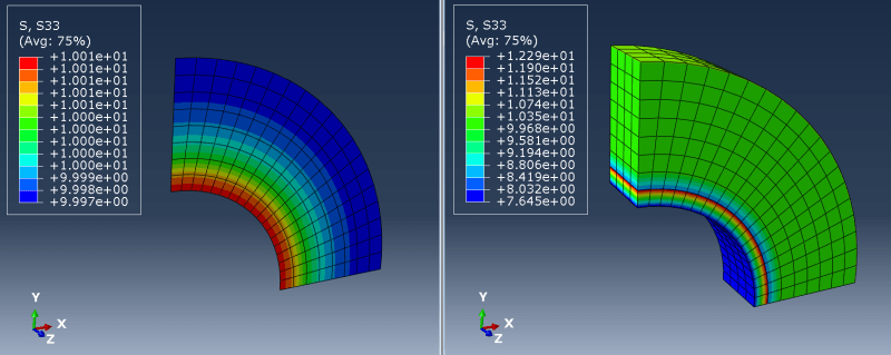
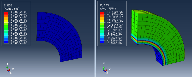
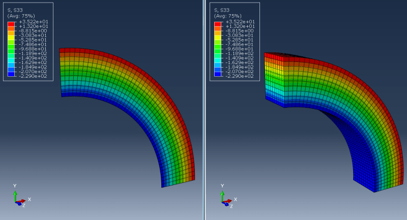
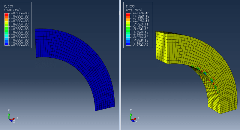
2) PLANE STRAIN (e.g. long pipe):
This one apparently requires fixing normal displacements for front and back faces of the structure but is it sufficient? Or should some additional boundary conditions be applied in the middle of the structure? I've heard about an approach in which front and back faces have equalized displacements and apart from that there's also a boundary condition applied in the middle (with normal displacements constrained). Does the number of element layers matter?
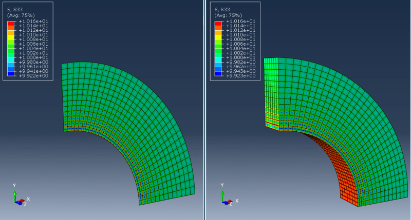
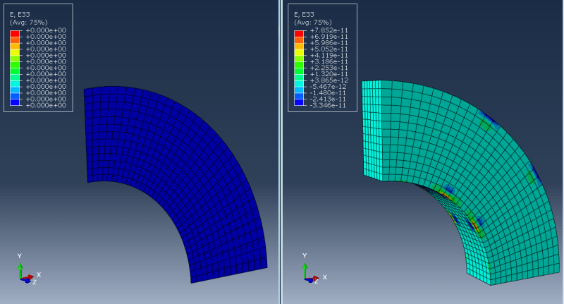
3) AXISYMMETRIC (e.g. pressure vessel):
Here I'm talking about taking a section (like 5 degrees or more) of a revolved model and applying such boundary conditions that it's equivalent to axisymmetric analysis. In such a case should I only constrain displacements normal to the faces of the cut (using local coordinate systems)? How does it differ from cyclic symmetry available in some FEA codes?
I've seen this thread: and would like to expand the discussion to a more general case. This topic has been puzzling me for some time and seems to be quite common among FEA engineers. And yet I haven't found a comprehensive answer anywhere. Some FEA codes don't support 2D (plane stress/strain, axisymmetric) analyses, making it necessary to solve everything in 3D using solid (volume) elements. I wonder how one can model such problems properly so that the 3D analysis is equivalent to 2D simulation and the same results are obtained. Here are my thoughts:
1) PLANE STRESS (e.g. plate subjected to tension):
From what I've seen in the referenced thread, this one is realized sort of naturally if the structure is thin and loaded in its plane only. So boundary conditions can be arbitrary (just to avoid underconstraint) and there's no need to fix normal displacements (in the Z direction) for front and back faces of the structure. Is that right? Is there a need to use only 1 layer of elements in the thickness direction (Z) thus preventing the use of tetrahedral elements?
2) PLANE STRAIN (e.g. long pipe):
This one apparently requires fixing normal displacements for front and back faces of the structure but is it sufficient? Or should some additional boundary conditions be applied in the middle of the structure? I've heard about an approach in which front and back faces have equalized displacements and apart from that there's also a boundary condition applied in the middle (with normal displacements constrained). Does the number of element layers matter?
3) AXISYMMETRIC (e.g. pressure vessel):
Here I'm talking about taking a section (like 5 degrees or more) of a revolved model and applying such boundary conditions that it's equivalent to axisymmetric analysis. In such a case should I only constrain displacements normal to the faces of the cut (using local coordinate systems)? How does it differ from cyclic symmetry available in some FEA codes?