I am modeling a 3 point bending test in Abaqus on a mouse bone (both tibia and femur) and in particular I want to assess the crack insurgence at the diaphysis level.
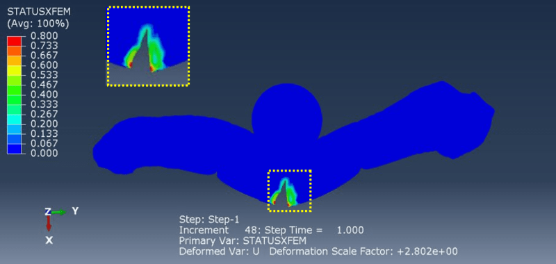
I was able to do it in a 2D femur geometry by calculating the STATUS XFEM
When I moved in a 3D tibia geometry I face some issues:
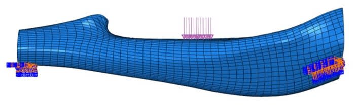
1) I had difficulty in assembling the bone with two supports as constraints, and with a load beam, therefore I just applied a load as y-displacement at the diaphysis and I constrained the bone at the epiphyses with encastres.
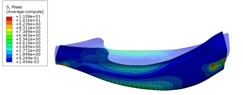
Even if I obtained realistic values of Von Mises Stress
 , I would like to move in a more faithful set-up as the one proposed by @magrimmelprez in the past 16 Dec 2016 in this forum. The researcher conducted a similar study with a 3PB test on a mice femur and human clavicle. Is there a way to interact with this researcher?
2) I tried to enrich the model with the special feature of a crack, but when I run the job, the software was not able to allow the crack generation and propagation. What can I do?
Thank you
I was able to do it in a 2D femur geometry by calculating the STATUS XFEM
When I moved in a 3D tibia geometry I face some issues:
1) I had difficulty in assembling the bone with two supports as constraints, and with a load beam, therefore I just applied a load as y-displacement at the diaphysis and I constrained the bone at the epiphyses with encastres.
Even if I obtained realistic values of Von Mises Stress
2) I tried to enrich the model with the special feature of a crack, but when I run the job, the software was not able to allow the crack generation and propagation. What can I do?
Thank you