Eng-Tips is the largest engineering community on the Internet

Intelligent Work Forums for Engineering Professionals

  • Congratulations waross on being selected by the Tek-Tips community for having the most helpful posts in the forums last week. Way to Go!

3D Force Analysis of a Hydraulic Crawler

Status
Not open for further replies.

ChrisDanger

Mechanical
May 15, 2012
33
0
0
ZA
I'm busy with a force analysis of a crawler, pictured below, using Excel. I've colour-coded the main parts into (static) body, yoke, [COLOR= #204A87]boom[/color] and nozzle. I've quickly drawn in the cylinders, but there are 3 pairs: the body/yoke pair swivels the yoke, the yoke/boom pair lifts and lowers the boom, and the final pair lifts and lowers the nozzle.

URL]


Here's a simplified diagram of the forces, where (generally) the cylinder forces are labeled F, and the reaction forces are labeled R. (I'm neglecting the weights and the nozzle suction force.)

URL]


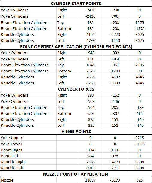
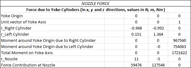
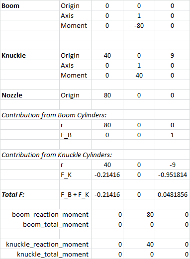
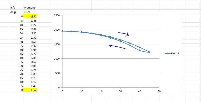
All I need to calculate is the resultant force on the nozzle for activation of the cylinders for any arbitrary position. I have the cylinder forces, and all the displacements calculated for whatever angles the respective hinges may be in. So now I just need the final piece of the puzzle: the nozzle force!

I'm running into several issues. I thought I could do this like a mechanism, using vectors. But with so many unknowns and the complexity of vector algebra, solving for multiple unknown vectors is impossible (it seems). I'm just really unsure how to proceed. Can I disregard the reaction forces and consider the cylinder forces acting in isolation, and simply sum their effect on the nozzle? Or do I need to write out the full equations for each "link", summing forces and moments to yield a full set of simultaneous equations, then solve that system?

Everything I've seen online just has simplified 2D analyses, like for backhoe excavators. I assume this is a fairly trivial problem for something like an FEA solver, but even that methodology is not the right tool I don't think.
 
Replies continue below

Recommended for you

Goodmorning Chris,

Here is a calculation for the yoke part only. The green cells can be filled in. Please modify the values as I do not know machine dimensions only angles and cilinder forces.
With the given values in the green cells Cell C34 gives the total horizontal moment that the yoke transfers onto the beam.
(for the YL cilinder the same goniometrics are used as for the YR cilinder however alfa is negative in that case)
If you want me to continu with the beam and nozzle please fill in the green fields.
 
 http://files.engineering.com/getfile.aspx?folder=3e56c3b7-6271-4cf2-a706-cd3cf656e363&file=Hydraulic_crawler.xlsx
Hi, thanks. I see you're using a different method, using trig instead of matrix algebra. I've managed to get some values for the Yoke contribution, which is fairly trivial since the axis is always vertical so one can work in the horizontal plane. For the other axes I've been trying to get an equation that yields the point on the hinge axis that makes a perpendicular vector to the nozzle (for the yoke it's just <x_nozzle, y_nozzle, 0>), hoping to avoid transforming the coordinate systems.

Anyway, this is the geometry I used as well as the values I got. (The first set of values are in mm and kN, but I had to change units for the final calculation because I was getting an odd (1000x too small) answer and confusing myself.)

I just used M = r x F to get the individual moments from each cylinder, summed them, then F = M x r / rr to get the resultant force at the nozzle.

PointsOfInterest_to3euu.png


NozzleForce_eugui1.png
 
That's awesome, thanks! I just finished the other two. I realised the symmetry meant that the perpendicular vector joined the axis at the mid-plane (to "uncross" M using r to get F). So that also turned out to be fairly trivial too. But it's great to know that you got the same answer for the yoke! Thanks again.
 
ChrisDanger,

I have hand-calculated another example, this time avoiding the special case with undefined forces due to the pivots and nozzle being coplanar. I have also changed coordinate systems and terminology to better match what you used.

Here's my setup, result, and verification in the form of MATLAB / Octave code:

[pre][tt]
boom_origin = [0, 0, 0];
boom_axis = [0, 1, 0];
boom_cylinder_moment = [0, -80, 0];

knuckle_origin = [40, 0, 9];
knuckle_axis = [0, 1, 0];
knuckle_cylinder_moment = [0, 40, 0];

nozzle_origin = [80, 0, 0];

nozzle_force = [80/9, 0, -1];
% my hand-calculated result

boom_r = nozzle_origin - boom_origin;
boom_reaction_moment = cross(boom_r, nozzle_force);
boom_total_moment = boom_cylinder_moment + boom_reaction_moment
% should equal [0, 0, 0] for equilibrium of moments

knuckle_r = nozzle_origin - knuckle_origin;
knuckle_reaction_moment = cross(knuckle_r, nozzle_force);
knuckle_total_moment = knuckle_cylinder_moment + knuckle_reaction_moment
% should equal [0, 0, 0] for equilibrium of moments
[/tt][/pre]

I believe your result would be [0.21416 0.00000 -0.04819], but obviously you should confirm. In any case, I'm pretty sure our answers differ drastically. This means you probably disagree with my verification method above, so I'm curious where you think I've gone wrong.


pylfrm
 
Hi,

Yes, I get the result you quoted at the end of you post. My sign is reversed though, so I get the moment equilibrium when I set [tt]boom_total_moment = boom_cylinder_moment - boom_reaction_moment[/tt]. I think this is because I get the force the nozzle exerts as a result of the moment, not the reaction on the nozzle.

Here are my values with your inputs. I'm not sure how you did your hand calc, but I can't see how you got [tt]nozzle_force = [80/9, 0, -1][/tt].

pylfrm_example_ypkidh.png
 
ChrisDanger,

Same method I originally suggested, setting up an equilibrium equation at each pivot and solving the resulting system. I used a Pythagorean triple (9^2 + 40^2 = 41^2) for the geometry to keep the trig simple. Note that this was done with with x+ to the right and y+ up.


boom equilibrium:
0 = 80 Nm + 80 m * Fy * 1 + 80 m * Fx * 0

knuckle equilibrium:
0 = -40 Nm + 41 m * Fy * (40/41) + 41 m * Fx * (9/41)


80 Nm + 80 m * Fy = -40 Nm + 40 m * Fy + 9 m * Fx

120 Nm + 80 m * Fy = 40 m * Fy + 9m * Fx

120 Nm + 40 m * Fy = 9m * Fx

120/9 N + 40/9 * Fy = Fx

Fy = -1 N

Fx = 120/9 N - 40/9 N

Fx = 80/9 N


Now that I think about it, you may actually able to use superposition to combine the yoke result with the boom and knuckle result. This will only work if the geometry is just right, i.e. the boom and knuckle reaction force never creates a moment at the yoke pivot, but I suspect that may be the case here.


pylfrm
 
Yes, the boom and knuckle hinges are always in a horizontal plane, and the resultant force is in the vertical plane that contains the yoke hinge.
 
ChrisDanger,

Okay, so you only need to solve a system with two equations and two unknowns. Does my method and result make sense now? Most importantly, would you agree that that the total reaction force at the nozzle must provide equilibrium of moments at both the boom and knuckle pivots?


pylfrm
 
I'm just skipping all the other calcs to suggest that the method of virtual work would probably be easier.

Since work is a force through a distance, allowing each cylinder to move a (very) small distance with a known force will result in the nozzle moving through some distance. Since work in = work out (neglecting all the usual suspects) then all one needs it the ratio of movement as a multiplier for the input forces to get the resulting output reactions.

Matrix wise, I believe this is the Jacobian of the kinematic matrix, but it can be done by simple geometry and a spreadsheet to determine sensitivities.

You can do the same with a CAD system and make small changes to the cylinder lengths and measure the nozzle movement.
 
Hi,
Nice to have different solution methods now.
The moment into the beam i found is max at centre position and turning cw or ccw doesn't make a lot of difference.
Knipsel_gwbkgz.jpg
 
Status
Not open for further replies.
Back
Top