Good afternoon all,
I have a problem which has really melted my brain this afternoon and I am hoping someone can offer some insight.
My company had recently designed and built a three phase thyristor bridge rectifier for our customer.
One of our customers requests was that each thyristor had redundancy, so for each thyristor position in a normal bridge rectifier, we have two thyristors sharing in parallel.
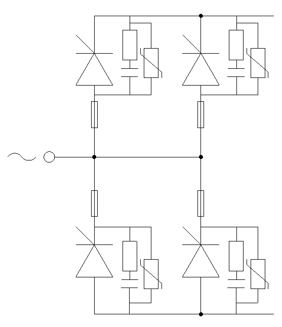
To keep general assembly size down, we supplied to our customer 3 individual phase limbs. Below is the basic circuit diagram of each phase limb with individual thyristor fuses and snubber circuits.
However, our customer is reporting that the thyristors are not sharing current equally, and in some cases, not at all.
Our customer sent one of the phase limb assemblies back to us for examination, and sure enough, they are not sharing.
One thyristor always takes full current, the other takes nothing.
We have removed the thyristors, heated them up to around 100'C (around 110'C junction temperature), run full PIV tests on them. They are fully functioning. We cannot find any fault with the thyristors.
We have even pulled thyristors from a different manufacturer out of stock and still get the same issue.
We have tried triggering the thyristors simultaneously, and individually one before the other, but to no avail.
Oddly, one thyristor ALWAYS takes full load, we'll call this 'Thy A'. If we trigger the thyristor which does share first (Thy B), it comes on and takes full load current. But the moment we trigger 'Thy A', then 'Thy B' switches off and all the current goes through 'Thy A' again.
I feel like we are simply missing something that should be obvious but it is escaping me completely.
Anyone have any suggestions?
I have a problem which has really melted my brain this afternoon and I am hoping someone can offer some insight.
My company had recently designed and built a three phase thyristor bridge rectifier for our customer.
One of our customers requests was that each thyristor had redundancy, so for each thyristor position in a normal bridge rectifier, we have two thyristors sharing in parallel.
To keep general assembly size down, we supplied to our customer 3 individual phase limbs. Below is the basic circuit diagram of each phase limb with individual thyristor fuses and snubber circuits.
However, our customer is reporting that the thyristors are not sharing current equally, and in some cases, not at all.
Our customer sent one of the phase limb assemblies back to us for examination, and sure enough, they are not sharing.
One thyristor always takes full current, the other takes nothing.
We have removed the thyristors, heated them up to around 100'C (around 110'C junction temperature), run full PIV tests on them. They are fully functioning. We cannot find any fault with the thyristors.
We have even pulled thyristors from a different manufacturer out of stock and still get the same issue.
We have tried triggering the thyristors simultaneously, and individually one before the other, but to no avail.
Oddly, one thyristor ALWAYS takes full load, we'll call this 'Thy A'. If we trigger the thyristor which does share first (Thy B), it comes on and takes full load current. But the moment we trigger 'Thy A', then 'Thy B' switches off and all the current goes through 'Thy A' again.
I feel like we are simply missing something that should be obvious but it is escaping me completely.
Anyone have any suggestions?