Continue to Site

Eng-Tips is the largest engineering community on the Internet

Intelligent Work Forums for Engineering Professionals

  • Congratulations KootK on being selected by the Eng-Tips community for having the most helpful posts in the forums last week. Way to Go!

4 point bending test in Femap 2

Status
Not open for further replies.

Hesy33

Materials
Feb 19, 2021
9
Hi all,

Note: I have read through many posts before posting here as I was not able to find a convincing answer.

My first post but a long time follower. :)
So please be kind If am using the wrong forum to post this.

I am trying to model a 4- point bending test of a ceramic composite.
But we treat it as a monolithic and isotropic material and hence no layering required.

From experiments, I have breaking load at 3000 N.
The material has an E=350 GPa and Flexure strength of 330 MPa.

I have applied the same load to see if the stress levels match. But I'm getting only 60 MPa for the 3 kN also deformations seem to less. So my model is clearly stiff.
I am meshing with Tet elements and have contact on bottom rollers and loads on curves. (I have tried other methods of loading and support but with no luck)

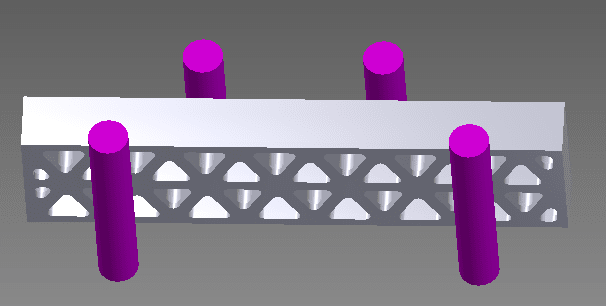
What is the best to model a 4 point bending test and what could be the problem in my model ? Attached is a picture of the FEA.
 
 https://files.engineering.com/getfile.aspx?folder=c03ce175-639c-418f-9cd8-4fabeff6e7af&file=Mesh.PNG
Replies continue below

Recommended for you

stress is "just" My/I (no material properties) ... so a hand calc should confirm (you were obviously expecting something more like 330 MPa.

plenty of elements ... TET10 or TET4 (don't use TET4).

How did your test fail ? (did it fail in bending ? impact load ??)

another day in paradise, or is paradise one day closer ?
 
Use hexmesh and use two symmetry planes to stabilize modell.
In addition - what type of contact between bricks and rollers you use contact or glue?
 
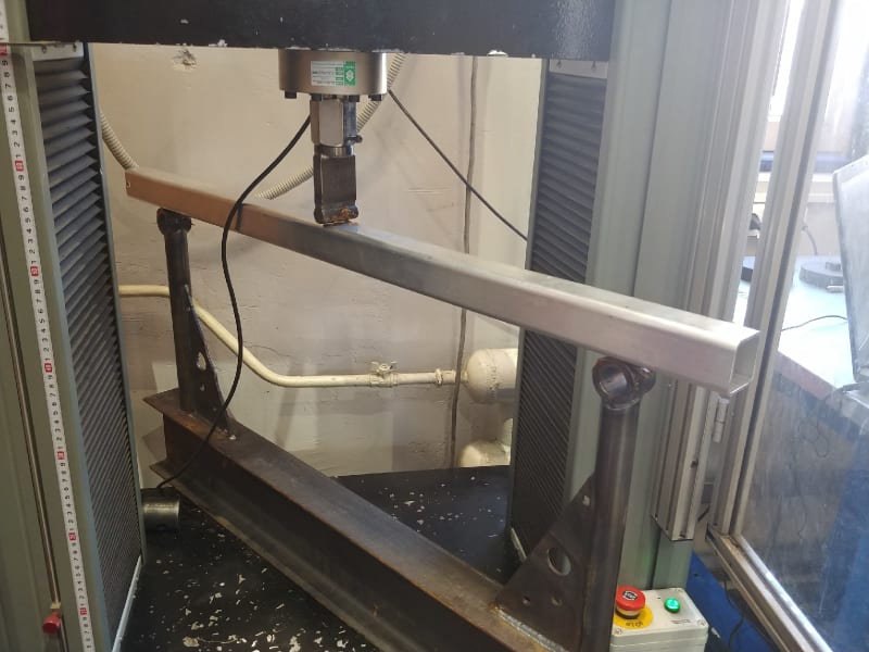
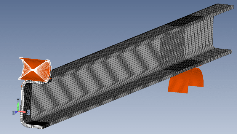
Here is an example of a 3 point bend test and it`s FEA model.
Here is how a test rig looks like.
W52y1fEs30w_mzmbuy.jpg

And here is FEA mesh, only 1/4 portion of beam was modeled.
1_gpqhlw.png

Two symmetry planes prevent all rigid body movement except vertical translation.
 
It is not a simple beam I am testing, it has a cells inside (cross section as shown).
@rb1957 , it failed under bending. It is a ceramic composite and hence brittle.

@karachun, The contact is a fritcional contact.
In the FE model, have you constrained the rollers to displace only in ther vertical direction?
What about load? If the load is applied on the roller, some of it is lost in the volume expansion of the roller itself, right?
 
Contact if frictionless. Roller coated with some grease to reduce friction.
One roller is fixed, the other roller can only move in a vertical direction.
Roller loaded with enforced displacement and roller modeled as rigid body, using RBE2 element. Therefore roller has no deformation.
 
stress is still My/I, ie not material dependent.

I would expect that most of the bending is carried by the three continuous longitudinal webs (and not much by the diagonal bracing webs).

Are you questioning the FEA stress ? 60MPa seems much less than the "flexural strength" of 300+ MPa ?? (or is this Ftu ??)
if so you can do a simple hand calc to check.

Are there stress peaks on the cross-section ? If locally it exceeds 300 MPa, and is brittle, then the house of cards will come crashing down.


another day in paradise, or is paradise one day closer ?
 
@karachun Thanks for the reply.
How did you calculate the enforced displacement which corresponds to the load applied in the testing machine?
 
@rb1957 Thanks for the response.

I understand that the stress is not material dependent.
Yes, I am expecting a strss range of 300 MPa which is the flexure strength of the material.
The Area Inertis is tough to calcuate given the complicated cross section. Is there a way I can take it out of Femap?

There are no stress peaks at the cross-sections excpet the small radii which can be carefully neglected.
 
like I suggested I'd use the three continuous longitudinal webs as a hand calc.

are you Sure E in the FEM is correct ?

Your testing should have measured deflection (to answer your question to karachun).

another day in paradise, or is paradise one day closer ?
 
Yes, the FE material input is correct.
I did a quick hand calc and I see a max stress of 25 MPa.
I have 40 MPa in Femap.

The material should not have fractured at this level.
What could be the reasons?
 
Ok, so hand calc "confirms" FEM ... I'd've expected the hand calc to be a higher stress than FEM, but maybe you're seeing a localised peak stress in FEM ??

Humm, so why'd it fail ?? what was the loading rate ? what does the fracture surface look like ?

Are you sure "flexural strength" is equivalent to Ftu ? (or is it some bending modulus ??)

another day in paradise, or is paradise one day closer ?
 
@karachun,

I modelled a rectangular beam with frictionless contact.
How can I model a remote force with an RBE element?

MOdel attached

@rb1957,
The hand calc was done with Hook'es law.
However from the experiments my cermaic composite does not agree with Hooke's law in the linear range.
How can me model such behaviour into Femap?

 
 https://files.engineering.com/getfile.aspx?folder=e8017f89-3c4d-407d-8de6-1c09d5046364&file=test.zip
You do not need remote force with RBE element, your model is already OK.
 
why an RBE ? apply the load to a node (or a line of nodes). It makes no difference to your model (since you are applying load to a cylinder that applies load to the beam).

what material definition did you use (non-linear) ? If same as your test, then you have specified a linear material (Hooke's law) ... which you say your material isn't.

If your material is non-linear, then you need to use a non-linear FEA solution.

another day in paradise, or is paradise one day closer ?
 
Just another follow up question here,

I have never worked with symmetric models before.
The model I shared for example, has a von mises of ~170 MPa.
But according Mý/I,it should show ~330 MPa.

Should I double the stress results? Why is the FEA results different? Am I missing something obvious here?

stupid question - the model is 1/4th but the roller which is the load is only 1/2. My reasoning is that I have to divide the load by 4 as well. Correct me if I am wrong.
 
yeah, I usually avoid using symmetry, who cares about a few elements ?

"double" ... no you do not double the results ... there is a mirror image of the modelled part on the other side of the symmetry plane.

double symmetry ?? ... sure, but excessive (IMHO). the model is 1/4, the load is 1/2 (as 1/2 the load is on the other roller (on the other side of the plane). The length-wise split is quite redundant (you should see zero bending here) ... you can just as easily model a 1" width and apply 1/W load.

another day in paradise, or is paradise one day closer ?
 
Status
Not open for further replies.

Part and Inventory Search

Sponsor