Eng-Tips is the largest engineering community on the Internet

Intelligent Work Forums for Engineering Professionals

40-ton timber arches collapse in Hickory, NC 35

Status
Not open for further replies.

bugbus

Structural
Aug 14, 2018
498
0
0
AU

Before:
c_v0gdsn.jpg

a_xq7ujk.jpg

b_bjiumg.jpg


After:
3_idudj9.jpg

2_cygatg.jpg

1_scwfo5.jpg
 
Replies continue below

Recommended for you

It is a bit alarming to me that nearly every picture containing steel exhibits welded joints that have pulled or cracked right at the root/HAZ.

If that rusty line on the inside edge of the loose twin socket bracket was where another piece of steel was butted prior to galvanizing, it does not not look like there was any fillet penetration whatsoever.

Edit: Not implying this is a trigger/cause. Perhaps a quiet indicator of a much larger issue...
 
I agree, welding is poor everywhere. As for the connector, it looks like it was continuously welded on one side only, possibly so that protruding weld did not interfere with the fit, lest costs were incurred for further prep or grinding. The counter argument is that when the structure collapsed, these connections were going to be destroyed one way or another.

Connector_Weld_Break_ftglbo.jpg

Photograph 21 and 14
 
I realize now that I've just presumed the frayed cable to be the south stay. I can't find any evidence to confirm that. (i.e. photos to trace the cable to its origin)
 
I really wasn't impressed with that "forensic report". If that really was the extent of the work done then it really isn't going to do it for me.

The thing that was interesting to me what that she didn't really look into that joint that failed and how it was modelled and designed.

The SAP model and the report don't say exactly how nodes 4 and 22 were modelled. With the relative stiffness and strength of the lower wishbone compared to the rather flexible section above it that joint design is where the failure probably lies IMHO.

I've said before that maybe a better design was to have one solid section going through that joint with two angled connections to the joint so in the SAP model 3,4,5 and 21,22,23 would be a single solid piece of timber and 28 to 4 and 29 to 4 would be bolted connections to the main solid spar.

To not even try to model this herself in SAP is a real budget job of a report IMHO.

Remember - More details = better answers
Also: If you get a response it's polite to respond to it.
 
In the photos shown here:


you can see the south cable is not broken, and is stretched taught. Note the indent on the pedestrian bridge southern handrail (see shadow in photo) made by the cable. The other railing also has a dent, though lesser.

It appears it's the north side cable that is frayed. Which is a surprise to me, as mentioned/implied in a previous post. With the direction of the fall, there should have soon been no load on the north side cable.

Also, you can see most of the sideways movement of the structure happened above the pivot points called nodes 4 and 22.


spsalso
 
spsalso (Electrical) 21 Jun 22 16:02 said:
... you can see the south cable is not broken, and is stretched taught.

There are two cables on the north and two on the south. One each side for both the upper and lower arches. The arches are two separate structures, unconnected. The cable which remains tight is for the upper arch whereas the frayed cable is for the lower arch and runs a random path along the ground which is easily confused with its counterpart.

From a design aspect, the report touches on an interesting aspect, modelling for wind load. It appears that wind load was considered for each arch standing separately but without consideration for any proximity to adjacent structures, in this case a twin arch immediately adjacent.

Modelling_deficiency_mwu9ev.jpg

Page 8
 
I wouldn't be the least bit surprised if the engineer who ran those calculations learns of the '35psf on the entire profile as if it's a solid wall' requirement from the forensic report. I would be even less surprised if they said they concluded the design was completely infeasible with that wind load within other parameters of the project, and so chose to reduce it based on engineering judgement. I get it...modeling it as a solid wall is a bit silly...but it also doesn't fit nicely into any of the categories for wind analysis that structural engineers typically use. So to reduce it without a more rigorous testing method (such as a scale model in a wind tunnel) isn't the best move. No doubt they felt the budget pressures...wind tunnel testing on a $750,000 structure? When pigs can fly...
 
Sym P. le,

Thank you for pointing out the four cables, as opposed to two. I do, however, wonder if the two arches WERE connected, after installation. If they were not, why wouldn't one, only, tip over? I supposed what could have happened is, when the lower arch tipped far enough, it started bearing on the north side cable for the upper arch. If it keeps going, it then also pulls the upper arch down, using the cable.

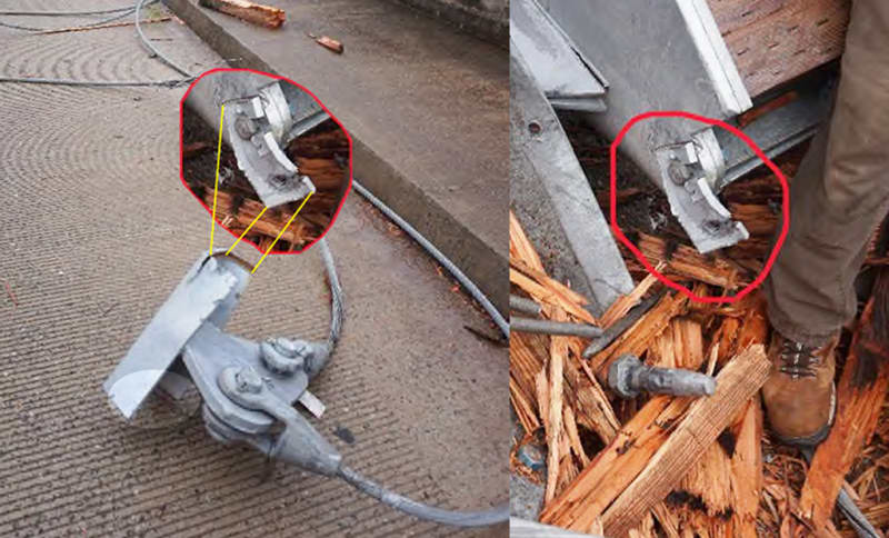
So, I believe you're saying one of the south cables snapped (the lower arch one). And the other south cable followed the structure down, as it tilted over.

There would then have been over 31 tons tension on the snapped cable, when it happened, to make the cable fail.

And the snapped cable is on the windward (south) side.


spsalso
 
Virtually impossible to say for the cable what is pre and post failure damage IMHO. The report is more than a little bit one sided and tries too hard to find a smoking gun.

Think this is a much smaller version of the FIU bridge. Very odd design, strange construction, no proper models or proven design methods. Probably very little independent review

Result, it fell down.


Remember - More details = better answers
Also: If you get a response it's polite to respond to it.
 

The jury is still out about the failure being precipitated by the failure of the cable... They likely don't have a clue about what caused it yet. The problem with the report that's out there is that it is poor and may not be correct. I hope the professional association is a little more on the ball... why lodge a complaint using such poor information?

Rather than think climate change and the corona virus as science, think of it as the wrath of God. Do you feel any better?

-Dik
 

I haven't seen any indication that the two arches are connected. With the lower arch nested under the upper arch, between its two stays, the collapse of either one would take the other with it.

One of the lower arch stays is badly frayed down to a few strands. It's as though it was taken near to its limit but just prior to failure the load was released. I think that lends to the argument that it was the victim of another failure. As I alluded to earlier it's strongly suspected that it's on the windward side but we need confirmation.

LittleInch (Petroleum) 21 Jun 22 19:46 said:
... smaller version of the FIU bridge.

I think from a structural design standpoint, this is far worse than FIU. This design didn't have a chance and the failure was sudden. There was no opportunity to protect the public or remedy the problems. FIU could have been salvaged had they taken appropriate precautions and undertaken to understand the as built structure (not what the final report said or the intended design).
 
I disagree... there were fatalities with the pedestrian bridge.

Rather than think climate change and the corona virus as science, think of it as the wrath of God. Do you feel any better?

-Dik
 
The failure of this arch structure has similarity to the FIU pedestrian bridge failure for the following:
1. Computer modeling appears to have been relied upon without having a complete analysis model.
2. The computer model appears to have been simplified for factors/scenarios that basic hand calculations would have called in to question the results presented by the computer analysis. Quite surprising, if the report by Dara Thomas is correct, that the design analysis only looked at the top arch and no moment control of the structure was employed during the analysis. Was the expectation the guy wires with very narrow included angles connected to relatively thin pinned joints at the arch apexes were going to provide all the necessary moment control?
3. The EOR has a stellar record and many accolades and has been an innovator in his field of design. Possibly, the EOR's reputation caused less scrutiny of the design analysis? Did the reputation of Western Wood Structures cause less scrutiny of the design?
4. During construction, failure modes were noted and remediation done but there may not have been a reassessment of the design analysis to account for the unexpected behavior of the partially completed structure.

This failure and the FIU pedestrian bridge failure are reminders to me to not get too casual or comfortable with my design expertise.
 
I read through the forensic report and I think the author found a significant modeling error but didn't really follow up on it. That is the cables were modeled as rods and not tension only cables. I am very familiar with STAAD and not SAP2000 and I am assuming they work in a similar fashion for compression elements. That is there is no buckling in the analysis and the compression rod could have taken quite a bit of load because in the model it would be a stiff element. This could be confirmed by looking at the compressive stress in the rod.

Assuming I am correct its not surpassing the structure was under designed for overturning since the rod would be like a kick stand on a bike.
 
So someone actually ASSUMED a 7/8" diameter rod that was approximately 50 feet long would accept any significant compressive load.

And who might this blindingly overqualified engineer be?


spsalso


...so, you can't push on a rope. Actually you can, you just reduce it's effective prestress! [pipe]

Rather than think climate change and the corona virus as science, think of it as the wrath of God. Do you feel any better?

-Dik
 
I have not read through the forensic report, but I certainly have used rods to mimic cables in RISA models. A key thing is to make sure to set them to tension only, so that the analysis program will turn the member off if it sees any compression (and also re-run the model without that member). I can't speak to what the EOR did, but the idea that you would use a rod to model a cable isn't crazy.
 
Status
Not open for further replies.
Back
Top