Continue to Site

Eng-Tips is the largest engineering community on the Internet

Intelligent Work Forums for Engineering Professionals

  • Congratulations KootK on being selected by the Eng-Tips community for having the most helpful posts in the forums last week. Way to Go!

4x holes as a Tertiary Datum ? 1

Status
Not open for further replies.

Rwelch9

Mechanical
Apr 22, 2020
116
Hi guys,

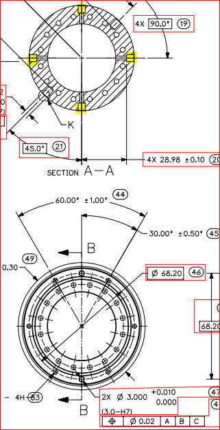
I have a print with 4 dowel holes that are equally spaced around a cylinder. Not on the top face face, holes that are breaking through the the external shaft itself.

So at the moment the DFR is as follows,

Datum A ( Plane )
Datum B ( Internal Cylinder )
Datum C ( 4x side dowel holes )

I am trying to work out how these 4 holes can constrain only 1 degree of freedom.

These are important features to the part, However I have two dowel holes on the top planar face, which actually orientate the part with the mating component which I felt should have been Datum C.


Thanks

R
 
Replies continue below

Recommended for you

In the short version - a planar reference controls 3 degrees of freedom. Only 6 degrees of control are possible. So how can three planes controlling 9 degrees of freedom be possible?

Answer - Only the uncontrolled degrees and non-redundant degrees get evaluated.

It seems like the 4 holes are controlling rotation about the axis of the cylinder, but why share what the drawing is like instead of a verbal description that leaves nearly unlimited doubt about the real configuration.

The specific question you ask needs to be discussed with the people who made the drawing and who approved the drawing. No one here can change the drawing.
 
Rwelch9 said:
I am trying to work out how these 4 holes can constrain only 1 degree of freedom.
I'm not sure what you're trying to work out. If we go with the situation as it seems (as 3DDave said), then the holes simply control the rotation factor, which is indeed 1 degree of freedom.
You'll have to explain more about why this seems strange. Is it because it's a group of holes rather than one hole which locks in that single DOF?
 
Belanger,

Exactly, A group of 4 holes especially 4 side holes, I have no idea how this would only constrain the final degree of freedom.

I could see setting up the DRF slightly different then controlling these 4 holes back to the DRF.

I will put a picture up soon with more details for you guys,

Thanks as always for the support

R
 

Rwelch9,

Is it possible that your datum selection is not accurate? It is very hard to guess without knowing the application/design intent and without seeing the mating part(s).

In addition, I assume 4 dowels will fit into those 4 dowel holes? So if you defined 4 holes as a datum feature (doesn't matter primary, secondary, or tertiary), they would have to be RFS/LMC and RMB (based on application), which makes it practically impossible to gauge the datum feature C.

My assumption is that you only need 2 datum features(?). And you will just have to control those 4 holes wrt A|B: 4X | pos | dia x (P) y | A | B | (you can also use B(M) instead of B depending on your application). I hope this makes sense.
 
Tarator

I do not think the Datum selection is not accurate, I was wondering if 4 side holes / counter bores as a group could even be a tertiary Datum ?

See attached print, the 4 highlighted counter bores are Datum C,


Thanks

R

we_ebmpdd.png
 
Yes. The four counterbores can be a tertiary datum.
 
3ddave

I will have a look the the standard again could not see anything 1st time round,

I didn't know how that would work checking the part manually or accurately with CMM software.

My thinking for the DRf is using the 2x 3dowel holes on the top plane to locate and orientate,

Then the counter bored positional to that DRF

This seemed more in keeping with the function of the part and easier to inspect.

Thanks for clearing up though that it is a valid call out.

R
 
It's valid - from the tiny sliver of information presented it's not certain to be useful. That's a conversation that either needs an NDA and a check for $10,000 payable in advance or you talking with the people who designed this or both.
 
Rwelch9,

Short answer - I would say that the callout doesn't violate any rules, but using a hole pattern as a tertiary datum feaure is dubious from a functional point of view.

If the pattern of 4 counterbores really doesn't constrain the rotational DOF relative to the mating part, then using specifying the pattern as the tertiary datum feature just creates unnecessary uncertainty and complication. It would be more straightforward to just specify one of them as datum feature C, and and use that for the tertiary datum feature in the position tolerance for the other 3. If the 4 counterbores really do orient the part relative to the mating part, then I would say that this design makes the constraint fundamentally susceptible to variation. The rotational DOF would be controlled in a very unpredictable way. On any given part, in general only one of the 4 counterbores would actually contact its mating feature. But we don't know which one - it would depend on the particular combination of location and orientation errors in each of the 4 holes, which would make one of them "stick out" further clockwise or counterclockwise than the others.

I realize that it's a common application, but using a hole pattern as a tertiary datum feature makes it difficult to achieve precise rotational constraint. In order to get that, the holes in the pattern need to be accurate relative to each other, and to the secondary datum feature as well.

Evan Janeshewski

Axymetrix Quality Engineering Inc.
 
axym said:
...using a hole pattern as a tertiary datum feature is dubious from a functional point of view.
I presume you mean only in the OP's case it would be dubious (holes around the circumference). Because I don't think we can make that statement in general. Think of changing a wheel on a machine: there might be a mating face, a pilot rim, but the holes -- as a pattern -- form the tertiary datum, stopping the rotational DOF.
 
J-P,

No, I meant it in general. By dubious, I mean that we need accurate control over several features in order to accurately constrain the DRF. I agree that a hole pattern might stop the rotational DOF on a wheel, but hopefully we don't use that DRF for a tight position tolerance on some other feature. If we do, then we need to tightly control the holes in the pattern or we will get an unpredictable DRF. Also, for things like car wheels there is additional unpredictability because the parts deform to some degree when the lug nuts are tightened.

There is some tolerance to be gained by designating one of the holes as the tertiary datum feature (with closer clearance on the mating feature) and the other holes in the pattern with larger clearance. In some cases, that extra tolerance could affect the cost of the part. In other cases where it's just as easy to make all the holes accurate to each other, it doesn't lower the cost.

Evan Janeshewski

Axymetrix Quality Engineering Inc.
 
Evan -- OK, that makes sense, because the tertiary-datum pattern would be setting up a DRF for a tight tolerance on some other feature. (That "other feature" might be a better candidate for a datum!)

Also, throughout this, no mention was made of having the pattern-derived tertiary datum be referenced RMB. That is a different discussion, but one that immediately caused me to question the practicality of using such a datum.
 
J-P,

Right, I was going to ask whether the datum feature C reference was MMB or RMB. Either option is problematic in some way. If it's MMB, then there will likely be datum feature shift/displacement. This is difficult to work with using most CMM software. If it's RMB, then I agree that this is questionable. It's highly unlikely that the mating part has four simultaneously-expanding pins.

Rwelch9,

Is datum feature C referenced MMB or RMB, just out of curiosity? You've already told us that the part doesn't actually get constrained on these holes, so trying to adhere strictly to the standard during inspection isn't going to be worth the effort anyway. This brings back memories of CMM inspection ...

Evan Janeshewski

Axymetrix Quality Engineering Inc.
 
Axym,
So now you see where simultaneous requirement come very handy. No need for tertiary.
 
Axym

Datum feature C is referenced RMB, like all our drawings there is never any Datum feature referenced MMB.

The component itself is located to the mating part using the Ø3 dowel holes on the top face.

These 4 counter bores are crucial in aligning another part to this however. So they are very important features although not necessary what should be my Datum feature.

My CMM software will really struggle to check these as a group.

All I can do is create line between the cylinders and create intersecting points etc.

Although if this was not a Datum feature I could check the cylinders individually to the DRF, this would give me maybe more accurate and repeatable results.


Thanks

R
 
Evan,

This is a common "issue" for the company I am working for, with no reliable solution in sight/ near and long term future.
Design definition in all over the place: the parts work/ assemble the same way with its mating components, but the parts are defined either with all holes (pattern) as tertiary, either one hole, either with no holes (no tertiary)--I guess it's a designer preference, even shouldn't be.

Am I correct? Or should this decision is left to the designer? If no, then who should define those parts? Quality (based on their known inspection methods availability)?

Any thoughts?


Status
Not open for further replies.

Part and Inventory Search

Sponsor