Rwelch9
Mechanical
- Apr 22, 2020
- 116
Hi guys,
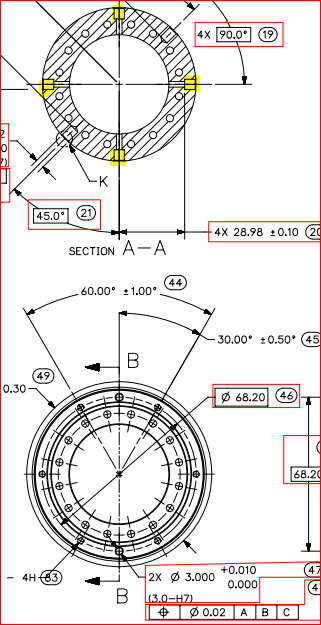
I have a print with 4 dowel holes that are equally spaced around a cylinder. Not on the top face face, holes that are breaking through the the external shaft itself.
So at the moment the DFR is as follows,
Datum A ( Plane )
Datum B ( Internal Cylinder )
Datum C ( 4x side dowel holes )
I am trying to work out how these 4 holes can constrain only 1 degree of freedom.
These are important features to the part, However I have two dowel holes on the top planar face, which actually orientate the part with the mating component which I felt should have been Datum C.
Thanks
R

