Eng-Tips is the largest engineering community on the Internet

Intelligent Work Forums for Engineering Professionals

  • Congratulations waross on being selected by the Tek-Tips community for having the most helpful posts in the forums last week. Way to Go!

5% rule between Kinetic energy and internal energy

Status
Not open for further replies.

Nir_k

Mechanical
Apr 13, 2021
39
0
0
TW
Hi all, I was running an explicit simulation on Abaqus. I wonder if I don't use the mass scaling to speed up my simulation, but the kinetic energy is far more than 5% of internal energy, does the result match the real phenomenon? Thanks.
 
Replies continue below

Recommended for you

Dear FEA way, I am doing an explicit simulation of external turning. I have tried many times that the final kinetic energy and internal energy never meet the 5% criterion whenever I do the mass scaling setting. Then I tried without mass scaling (and without setting the loading rate), and the final results also did not meet this 5% limit. The results obtained without mass scaling can ignore the 5% limit, right? Secondly, I don't understand what the loading rate is. If I set the boundary condition as displacement, I know that the velocity is the loading rate. If it is a stamping process, I also know that the drop rate of the punch is the loading rate, but if I set the boundary condition as velocity, what is the loading rate? How do I change this loading rate? Thanks!
 
What I mean is that the process may happen too fast in the simulation (too high velocity or too small step time). Manufacturing processes are often artificially sped up in explicit quasi-static simulations to reduce the analysis time. However, this may lead to undesired effects in form of high kinetic energy and thus the inertia starting to play important role.

Keep in mind that you should subtract the contribution of rigid bodies from the global kinetic energy before evaluating it.
 
Hi FEA way, thanks for your answer, the boundary condition I set for my circular tube workpiece is the angular velocity, which is 628 radius/s(100 cycles/s), and the velocity of my tool is 200 mm/s. The step time is 0.02s; I feel the angular velocity in simulation isn't high-speed compared to the actual external turning process. Besides, my tool is a shell at first because I don't want to set the rigid body constraint. I don't know whether it affects the energy comparison or not.
boundary_condition_tb88ot.png
 
Can you attach the ALLKE vs ALLIE plot that you obtained ?

To remove the contribution of the rigid body you can restrict the energy output to deformable parts.
 
Dear FEA way, the following picture shows ALLKE vs ALLIE, and I have restricted energy output to the workpiece, but it obviously doesn't meet the 5% requirement. The mass scaling factor is 100, and it takes me about 5 hours[sadeyes].
energy_comparison_emutdf.png
 
What about the other outputs - do the remaining energies look correct ? How about the contour plots and animated deformed shape of the model - do they agree with the expected results ?

With these conditions of the analysis, the significant contribution of kinetic energy might be unavoidable. Be careful when using mass scaling for this type of problem.

If you can share the .cae (or at least .inp) file, I will take a look at it and assess whether this analysis appears correct to me.
 
I had to apply a mass scaling factor of 1000 to solve this in a reasonable time even on a good computer. For debugging it's better to make the mesh much coarser until you are sure that the analysis works correctly.

Try replacing the kinematic coupling constraint applied to the back of the workpiece with a rigid body constraint. Also, the kinematic coupling applied to the tool is redundant since you already use rigid body constraint there.
 
Dear FEA way, I appreciate your patient answer.
I have tried so many times, including the below parameters setting.
setting_uufwqz.png

but the result shows that The layer of mesh where the workpiece constraint surface(coupled with RP) is located disappears, and the workpiece rotates only at a small angle. I think it may be because the mass scaling factor of 1000 affects the inertia of the workpiece motion. Just as the below picture shows.
firstly_mx7r5p.png
second_frame_akzqqk.png

Besides, I don't understand the meaning of "replacing the kinematic coupling constraint applied to the back of the workpiece with a rigid body constraint." Do you mean that I should constrain the left cross-section of the workpiece to another rigid body and give an angular velocity to it? By the way, it would be better if you could share the debugged .inp file you have just done.
 
What I means is that you should remove all the kinematic coupling constraints. Instead, define a second rigid body (one is already used for the tool) and utilize it to constrain the back face of the workpiece. The rest can stay the same - you can apply BCs to ref node of a rigid body constraint in the same way you did it with ref node of a kinematic coupling constraint. I haven't done this yet with your model, it was just a suggestion.

Can you share the .cae file as well ? It would be much easier to make the necessary modifications to your model and run some tests.
 
I just checked your .inp file, here are my 2 cents regarding minimizing the KE output:

1) Increase your step time, as a previous user said, to control KE you will need to apply the velocity/displacement BC over a longer period of time; might require some trial and error. Another solution would be to use slower velocities.
2) Use the smooth amplitude function instead of the tabular one to apply your velocities. This will limit the sudden jerks or "noise" in your energy output.
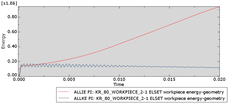
3) Again, as the other users pointed out, you need to look at the whole energy output and monitor each energy output individually to guarantee the quality and accuracy of your solution. If you want to maintain quasi-static conditions in your simulation, then yes keeping KE in check is essential. If you're running an impact analysis, a sudden increase in KE is expected.
4) I think your mesh is too fine. In explicit analysis the stable time increment is controlled by the material properties and size of the element. Since you want to limit the mass scaling factor to control KE, try making the mesh a bit coarser to get more efficient run times.
5) Most of the points I have pointed out are mentioned in detailed in the manual. Go through the explicit dynamics section, and more importantly go through the example problems in the getting started with abaqus manual. The "circuit drop" and "channel forming" examples have some good information regarding explicit analysis.

Hope this helps, good luck.
 
Dear FEA way and g.alshamsi, Please accept my heartfelt thanks. I will modify my simulation model furtherly as per your suggestion.
 
Status
Not open for further replies.
Back
Top