Continue to Site

Eng-Tips is the largest engineering community on the Internet

Intelligent Work Forums for Engineering Professionals

  • Congratulations KootK on being selected by the Eng-Tips community for having the most helpful posts in the forums last week. Way to Go!

500 RPM 8000 kW hydro generator dimensions

Status
Not open for further replies.

Rodmcm

Electrical
May 11, 2004
259
Hi
Would anyone be able to share the dimensions of an 7 or 8MW 500rpm (12p 50HZ) horizontal synch generator
 
Replies continue below

Recommended for you

Too few inputs. Please complete your generator specs. You could find better luck if others will be given ideas about voltage, winding preference, pitch, local environment, etc.
 
I have not seen any of these, so I can't help you. I also doubt most of us have seen these.
That said I have seen larger and smaller for 60Hz and lower speed, so that would not help.
I also don't think these are off the shelf devices, and must be custom made.
Not much help, but a perspective of why you may not get answers.

If you want an idea of the size, compare it to motors of similar size, speed, and ratings.

So why do you want synchronous? Would an asynchronous unit work?
 
Geometry will be based on the torque requirement (power per speed), the desired efficiency, the operating power factor, the magnetic flux being transferred across the airgap, and the voltage of the winding. Since several of these factors are unknown, all I can give you is an approximate volume of the magnetic material in the core. The actual "exterior" dimensions of the machine are going to be somewhat larger (in both length and width/height).

One end of the scale is a "sausage": stator core is 1.2m diameter x 3.3m length (which is going to have lots of problems with airflow, among other things).
Other end of the scale is a "pancake": stator core is 3.25m diameter x 0.5m length (which is going to be great for cooling, but a pain in terms of structural strength).

The real unit will fall somewhere between these two extremes.

Converting energy to motion for more than half a century
 
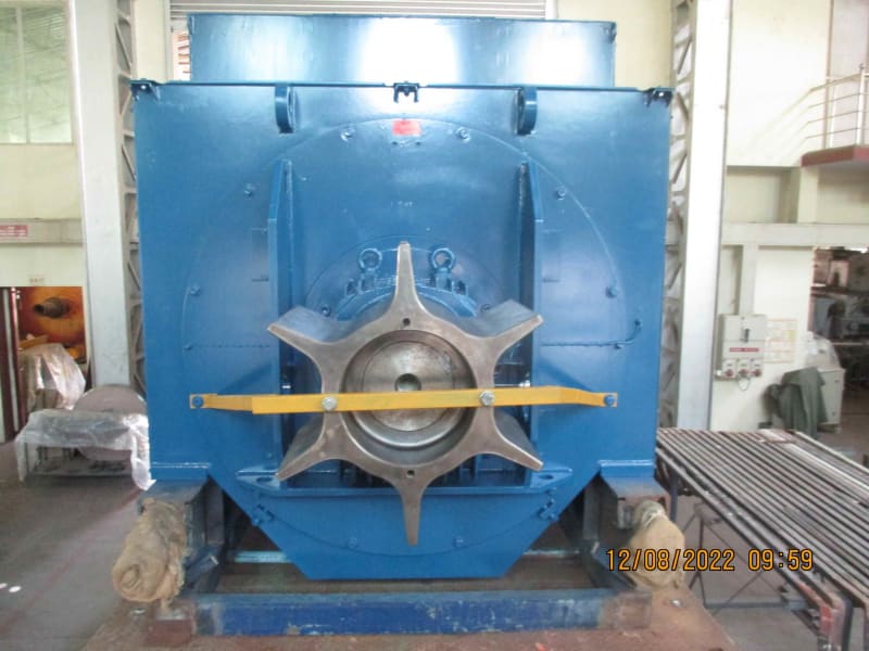
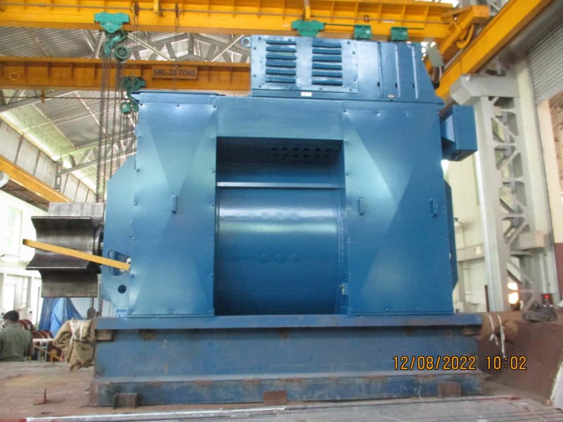
8 MW, 8 pole open ventilated generator rewound (6.6 KV to 11 KV conversion) in our shop.

30 tons / 12 ft x 8 ft x 9 ft (H) app.

A similar 8 MW, 12 pole machine will likely have 20% bigger size and would weigh probably 30% more.

01_as9443.jpg


02_fgud9g.jpg


Muthu
 
Muthu,

Is the generator driven by a diesel engine with soft coupling?

Walt
 
Thank you all
Its very hard to get information during the planning stages of a project from manufacturers, especially when asking for characteristics and dimensions. Plenty of brochures around, and lots of info on standard 2 and 4 pole items. Hence the call to this forum. Thank you for the response and to Muthu for a very definitive answer
 
Hi Walt

Yes, it's a diesel. The client is an IPP and bought this used 6.6 KV generator which we rewound for 11 KV to match his other 11 KV DG sets. Running well for two years now.


Rod

Unlike 2,4 or even 6 pole, multipolar generators are custom designed and built and the few OEM's may not provide all the details until they get their purchase orders. One option for you is to work out the economics of using a 500/1500 RPM gear box and go for a standard 4 pole generator.

Muthu
 
What are the basic construction differences between a Synchronous Generator and a Doubly Fed Induction Generator.
That is the rotors and stators.
Can this principle be used to increase the frequency of a generator with a given pole count and RPM?

--------------------
Ohm's law
Not just a good idea;
It's the LAW!
 
Yes Muthu an option... probably just as hard though to get info on a 7MW reducing gearbox!
 
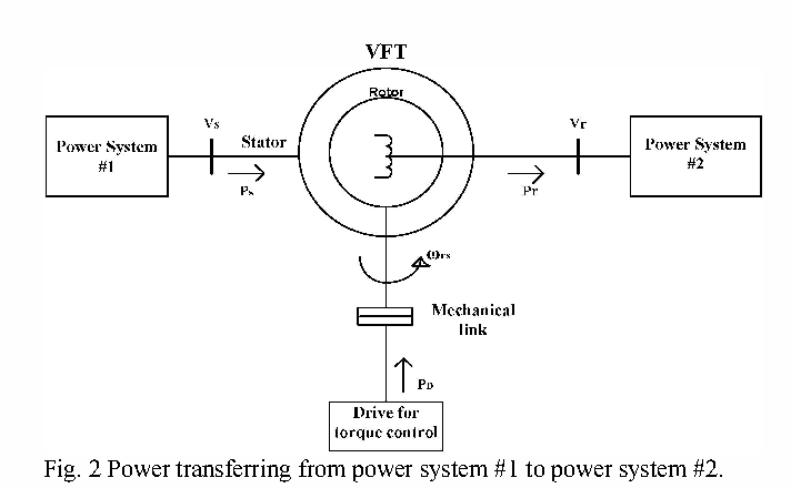
What Watoss is describing is (I think) called a Variable-frequency_transformer
[URL unfurl="true" said:
https://en.wikipedia.org/wiki/Variable-frequency_transformer[/URL]]General Electric installed a 3 × 100 MW VFT substation in Linden, New Jersey, in the United States in 2009. It connects the power systems of PJM & New York Independent System Operator (NYISO). This installation is in parallel with three existing phase-shifting transformers to regulate synchronous power flow.
Not many installed.
2-Figure2-1-1601639463_bnetbd.png

Power transferred is proportional to shaft torque.
Frequency change is proportional to shaft speed (and pole count).

The parts could be rearranged, to make this look like a wound rotor variable frequency motor setup used as a generator. The control scheme would be challenging, but the shaft speed need not be constant for constant frequency output.
 
Rod

12 pole machine
Cons: Less efficient, costlier, bigger footprint, heavier (crane), long lead time.
Pros: No gear box. Less noisy. Less wear & tear hence less maintenance cost

4 pole machine
Cons: Gear box with efficiency loss. Noisier. More wear & tear hence more maintenance cost.
Pros: More efficient, cheaper, smaller footprint, less heavy (crane), short lead time.

We just did a rotor rewind of a 36 MW, 3000 RPM generator with 5100 RPM GT via gearbox.
So, such large capacity gearboxes more readily available than 12 pole generators.

Personally, I would go with the 12 pole machine for a long term cheaper owning cost.


Muthu
 
Interesting fact: the GE variable frequency transformer installation in New Jersey is the small one.

The big one is located on a small island in the Saint Lawrence River, on the Canadian side of the border. It too has three units: each 600 MVA. Each has the rotor speed/position/power angle controlled by a DC motor rated 3500 hp at 0.1 rpm. Yep, one-tenth of a revolution per minute. The rotor never moves more than a few inches in either direction at its diameter. The units are connected to provide an "airgap" to isolate the power grids of New York State, Ontario, and Quebec - so there isn't a repeat of the catastrophic avalanching type of fault that occurred in the early 1990s that took out a large chunk of the northeastern power grid (in both countries).

As far as the basic difference between a synchronous machine and a doubly fed induction (also known as a Wound Rotor design) is that the synchronous rotor is fed by DC. The induction rotor is fed by AC, typically as a three-phase supply. Both stators are three-phase AC windings.

Converting energy to motion for more than half a century
 
Warning rabbit trail
Location of the Lindon gateway can be seen on the PJM Interregional Map.

Load-flow at Lindon. Actual load follows planned load much closer than any other gateway.

I found this, attached. Transient and Dynamic Modeling of the New Langlois VFT
Asynchronous Tie and Validation with Commissioning Tests
This circuit has a 100MW capacity as of 2022. Reference
 
Status
Not open for further replies.

Part and Inventory Search

Sponsor