Eng-Tips is the largest engineering community on the Internet

Intelligent Work Forums for Engineering Professionals

625 Microstructure

Status
Not open for further replies.

AH_AK

Mechanical
Jul 27, 2022
13
0
1
US
Anyone here work with 625 regularly that could comment on whether a microstructure we are seeing is normal/typical?

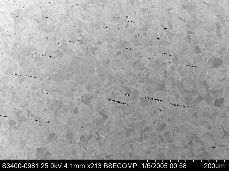
We have not etched yet and are using BSE and EDS on the SEM to differentiate phases in a polished specimen. We don’t have EBSD so the identification of phases is a bit loose. We do not appear to have laves phase, but we have some relatively large Nb-rich intermetallic stringers that are not on GB’s. I am not seeing these in the literature.

This microstructure seems atypical and potentially problematic from a fatigue/ductility standpoint. This component was relatively low stress (5 ksi), low temperature (200F), and in a reatively innocuous environment (air). It suffered a brittle failure with almost no ductility. The component had about 15% CW and for some reason we can’t figure, was not annealed (based on hardness and microstructure).

If anyone has expertise, I will post or PM the images.
 
Replies continue below

Recommended for you

I would be glad to help, but there are more questions.
Do you have mechanical properties for the sample?
Are you sure that no fatigue is involved?

= = = = = = = = = = = = = = = = = = = =
P.E. Metallurgy, consulting work welcomed
 
The average hardness is a little over 300 HV.

We haven’t cut test strips for mechanical testing yet. That may not even be an option (explanation below).

Fatigue is definitely a possibility. This is 0.030” wall 2”OD tube and failed at a 90 degree bend (welds are all remote from failure). It was rigidly clamped and almost certainly subjected to fluctuating stresses from vibrations and/or thermal cycling.

We are starting fractography and will be on the lookout for striations. Unfortunately, some of the pieces weren’t recovered and the operator repeatedly “reassembled” the ones that were, so there is a lot of mechanical damage on the fracture surfaces.

Based on the described events, the turbine was shut down and then when it was restarted they suspected a leak due to process temperatures being abnormal. It popped before they had a chance to investigate. It appears they had a 2 inch through crack that was leaking air for several days before the final failure. Unfortunately, the 2 inch crack that arrested got badly abraded by the leaking air.

Preliminary steroscopic investigation of the fast fracture (non-abraded) regions didn’t give too much info. No chevron markings, beach marks, or obvious fracture surface changes on first inspection. I did notice stepping, which I tend to associate with crack coalescence (i.e. ratchet marks), but there were a ton of very small steps throughout which made me think either we had a bunch of small surface cracks that linked up during fast fracture, or, there is something I am missing, and the stepped appearance can be explained by some other mechanism.

I am going to try some light flexure to open up and locate some closed surface cracks under the stereo scope.

This is a “informational” failure analysis. They plan to send everything to the manufacturer, so we are being told to make the minimum number of cuts to get some info for them. Silly, I know, but we are not a full service lab and really only handle failures that aren’t bound for litigation, so we are used to odd constraints on what we can and can’t do with the sample.
 
do you have a COA to see if the carbon content high? if you are certain there is no Laves phase (most detrimental to ductility), the culprit is probably NbC which formed at the end of solidification, very stable and hard to be eliminated at solution. 15%CW could lead to pre-existed cracks perpendicular to the Nb-rich bands.
 
The NbC by itself isn't bad, but if it isn't evenly distributed it causes real issues.
There are two HT conditions for 625 in most specs.
One is a full solution anneal and the other is sub-critical.
I would put the bending itself as an outside chance of causing issues.
The over-restraint is more likely the problem.
When things expand the stress goes somewhere

= = = = = = = = = = = = = = = = = = = =
P.E. Metallurgy, consulting work welcomed
 
MagBen and EdStainless: I am unfamiliar with the acronym COA. We plan to do spark OES to get accurate bulk composition data once we get approval to excise and flatten a sufficiently large piece of material. I have attached a BSE (compositional contrast) image of the LT plane. The small white/bright particles at GB's appear to be metal carbides based on EDS. Occasionally, we will see higher Si, ostensible a lave phase, but that is not widespread. I am not sure how I would go about differentiating lave phase without EBSD. The dark stringers are what stood out to me as a red flag, mainly because I have not seen anything on this scale in the literature.

EDS scans of the dark particles are "odd". They are very rich in Ti (the most abundant element in this phase, >30 wt%), rich in Nb (compared to matrix), poor in Mo (compared to matrix), AND rich in Nitrogen?? Due to the nature of EDS, I am always careful with light elements that have single peaks overlapped by a heavier elements. In the case of Nitrogen, its peak overlaps heavily with the first peak of Ti. I have seen absolutely nothing about nitride intermetallics in 625, so I am inclined to exclude Nitrogen manually from the EDS analysis, as it is likely just titanium that is being misidentified due to the peak overlap. Interested to hear your thoughts on this. Am I missing some relatively common processing mistake that would introduce nitrogen and nitride inclusions, or is this obviously a peak overlap error? We have ultrapure argon hooked to the OES for analyzing very low nitrogen in lean SS, so if N peak is not an error, I am hoping it'll pop again when we do OES.
Some quick web searching produced this: Link, which makes me even more prone to exclude/ignore Nitrogen from our EDS results.
File07_krdkdc.jpg
 
no attachment.

COA = certificate of analysis.

Suspect the white/brighter phase was Laves, while dark particles carbides/nitrides. Heavier elements shown in SEM brighter, lighter be darker.

Ti loves N, you may not want to exclude nitride.
 
In this alloy the Ti plays double duty, both to strengthen and act as a stabilizer.
So all of the C and N should be in compounds with Ti.
I wonder if the stringers are actually oxides (slag, trash) from the melt and cast.
Who melted this material?
I presume that since this is thin wall tube it is welded?

= = = = = = = = = = = = = = = = = = = =
P.E. Metallurgy, consulting work welcomed
 
Titanium nitrides and carbonitrides are easily identifiable by their morphology and color when observed under an optical microscope. The nitrides are golden-yellow and the carbonitrides more lavender-like.
 
There are some great optical tint etches that work on these alloys.
Even just light oxidation produces some good optical effects.

= = = = = = = = = = = = = = = = = = = =
P.E. Metallurgy, consulting work welcomed
 
All,
I am going to investigate the white particles further to try and discern between laves phase and carbides. We were seeing high C signals, but looking at our matrix readings I am starting to think we may have some carbon surface contamination. I'll ultrasonicate it briefly in alcohol and try EDS again.

Would the titanium nitride particles be yellow in the as-polished condition, or, after etching. What morphology would be expected? Blocky? I will have a look on the light microscope and see what sort of contrast I can get in the as-polished state.

I will look into tint etchants that may help me distinguish between carbides, nitrides, and gamma' or gamma'' (can they get this large if grossly overaged?)
 
Titanium nitrides are easily identifiable even in the as-polished condition (bright yellow cubic). In the case of titanium carbides, they are greyish-lavender with a more irregular shape.
In any case, what is observed in the image does not appear to be any of them. You will probably find some of them (in almost all titanium stabilized alloys they are found) but, in my opinion, not in that quantity and grouped that way.
 
The particles were yellow on the optical scope so I guess the EDS Nitrogen signature was not erroneous. Makes sense as well that they are dark on the BSE detector due to relatively low average Z.

Unless someone would like to chime in with information on how titanium nitride stringers on this scale would be acceptable/normal, I am prone to label this a material manufacturing defect. I'll let the manufacturer dive into how it happened. It explains quite reasonably the multi-site fatigue damage that preceded the brittle failure.

Thanks to everyone that replied.
 
Status
Not open for further replies.
Back
Top