Continue to Site

Eng-Tips is the largest engineering community on the Internet

Intelligent Work Forums for Engineering Professionals

  • Congratulations cowski on being selected by the Eng-Tips community for having the most helpful posts in the forums last week. Way to Go!

A(M)-B(M) co-datum

Status
Not open for further replies.

greenimi

Mechanical
Nov 30, 2011
2,391
What is the best way to take advantage of datum feature shift offered by A(M)-B(M) callouts.
(Software Calypso version 2014 5.8.2 service pack 5)

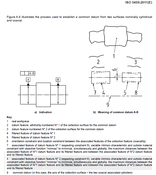
See attachment ISO 5459:2011 for A-B concept (shown RMB per ASME Y14.5 terminology)

I would like to know how A(M)-B(M) is calculated and how to use this datum feature shift?

co-datum_axis_ISO_5459_-_Copy_qjqarn.png
 
Replies continue below

Recommended for you

greenimi,

I don't see a datum shift anywhere unless you specify stuff at datum[ ]MMC. Out in the real world, that would be a long shaft that separated the two datum features. I strongly prefer my Feature Of Size (FOS) datums to be accurate. Your figure illustrates why.

Your datum simulator would be a pair of accurate holes at MMC[ ]diameter. If you do specify runout or position at datum[ ]MMC, we can wiggle the ends around in the holes to make things like up. If I inspect a part and pass it that way, would it meet your requirements?

--
JHG
 
drawoh said:
I don't see a datum shift anywhere unless you specify stuff at datum MMC

The print I am working with has A(M)-B(M)


drawoh said:
If you do specify runout or position at datum MMC

I think runout does not allow MMC's.

drawoh said:
we can wiggle the ends around in the holes to make things like up

I do not have a gage available so no wiggle around datum simulators. The part is measured on the CMM so how would you do it ?
 
I would like to know how A(M)-B(M) is calculated and how to use this datum feature shift?

For most application examples, there is a maximum material modifer(MMC) on the tolerance zone if there is a maximum material modifer(MMB) on the datum features, so I will think your question is based on this FCF
Position|ØX.XX(M)|A(M)-B(M)|.
When a position tolerance is used on coaxial features of size like this case, I will think there is no datum feature shift happened since they are self-datum, their size already used on the bonus calculation, therefore the size can't be used again to calculate the datum feature shift.

Season
 
SeasonLee said:
so I will think your question is based on this FCF
Position|ØX.XX(M)|A(M)-B(M)|

No Season, I am really talking about this callout

Position|ØX.XX |A(M)-B(M)|

RFS to the controlled feature, not MMC to the controlled feature.

MMB only for datum features.

 
In a physical gage one would jiggle the part until the feature tolerance was met or until it was clear there was no solution where the feature and datum feature references could simultaneously be met.

This may not be a function the Calypso software can perform. That is a discussion for Zeiss.
 
Position|ØX.XX |A(M)-B(M)|

I haven't seen this kind of callout so far, I will ask the designer what's the meaning of MMB here since the controlled features (also known as datum features) have been held by the shrinkable tube (RFS callout), there isn't any datum feature shift at all.

Season
 
Can't Calypso measure the actual features and create a combined "envelope" via some algorithm?
 
Belanger said:
Can't Calypso measure the actual features and create a combined "envelope" via some algorithm?

Yes, Probably it can.
Then how would you take care of the datum shift? Which is the datum shift?
The difference between what and what on this scenario of A(M)-B(M)?

 
SeasonLee said:
what's the meaning of MMB here since the controlled features (also known as datum features) have been held by the shrinkable tube (RFS callout), there isn't any datum feature shift at all.

There are multiple features that have the same datum reference frame DRF: A(M)-B(M) some of them are RFS some of them are modified at MMC, but AGAIN that is not the issue.

Just for clarity:
Datum feature A, cylindrical surface is modified at MMC and is defined from A(M)-B(M)
Datum feature B, cylindrical surface is modified at MMC and is defined from A(M)-B(M)

Lets say, for example, profile of a surface to A(M)-B(M) (no MMC on the profile controlled feature).

Then how the CMM will qualify / take advantage of the MMB's?
 
Imagine fig 9-6 from 2009 (ASME Y14.5-2009), BUT:
- instead of total runout for datum feature C is position and DRF is C(M)-D(M)
- instead of total runout for datum feature D is position and DRF is C(M)-D(M)
(I know you have to add some Ø symbols, but that is irrelevant for what I am asking)

Then some intermediate steps are dimensioned with profile for location and position for cylindrical surfaces to C(M)-D(M) -regardless if the actual features are modfied at MMC or not---

So, again, how Calypso (or if you have experience with PCDMIS) will use the datum feature shift?

 
It's just a math puzzle: can the actual features be placed within the allowed tolerances while meeting the given constraints. There may in fact be no datum shift allowed for some part variations.

What they should do is gather a few thousand points on each surface and shift them to be within the datum feature boundaries and fit the axis of the considered feature within its limit. It may attempt to minimize the deviation between the feature axis and the true position. If there are multiple simultaneous datum reference frames in other FCFs it may shift the collected surface points and derived axes to produce some collective minimum.
 
Status
Not open for further replies.

Part and Inventory Search

Sponsor