SofiaB
Civil/Environmental
- Jul 9, 2020
- 27
Hello everyone!
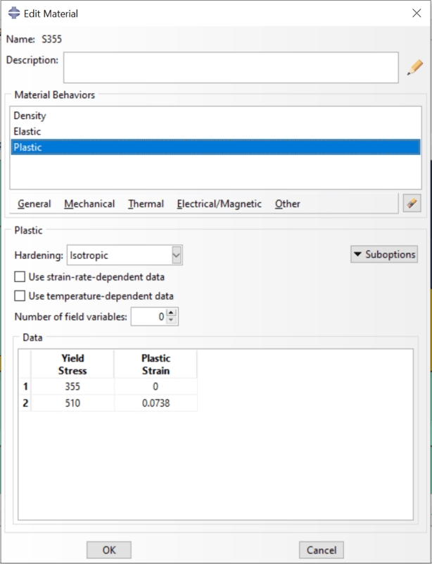
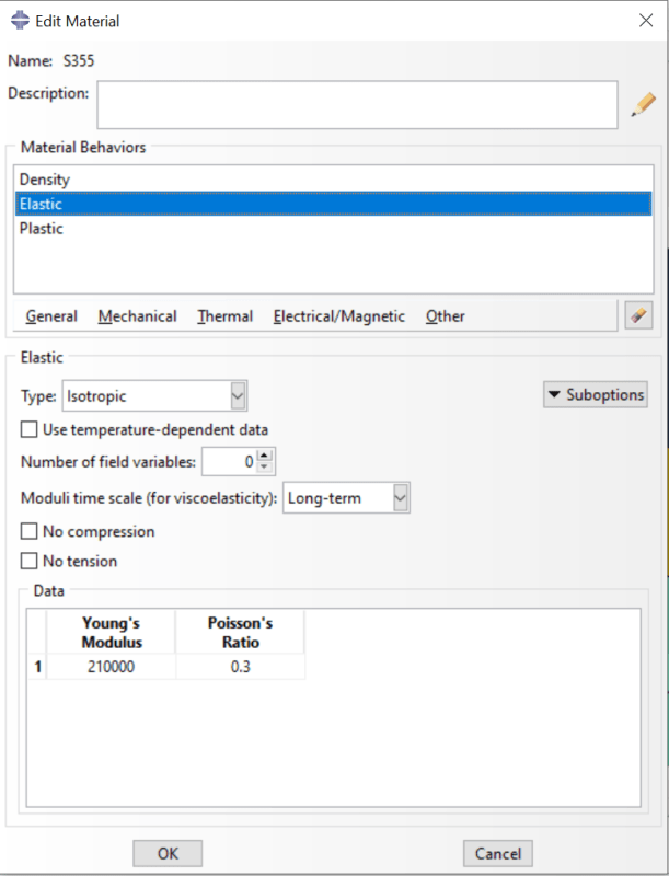
I am analysing an SHS steel truss, simply supported, with concentrated forces (in Newtons) applied in the top nodes. The loads are applied in reference points that are constrained, type coupling, to the section of the chord. All the top nodes have a boundary condition to prevent out of plane displacements.
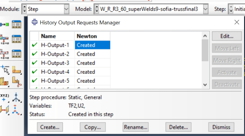
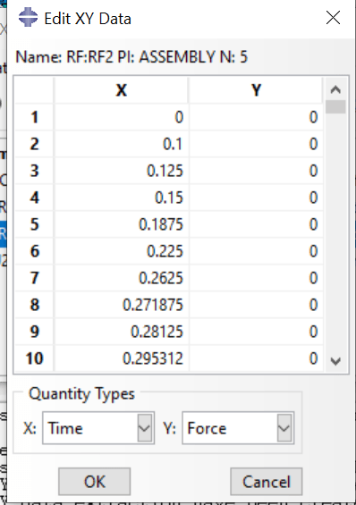
Since what I want to achieve is the force-displacement curve of each of the truss nodes in the history output I requested the TF2 and U2 variables. The problem is after the analysis is completed, the RF2 for that node does not show any values. Apart from that, the displacement increases but after a while reaches a plateau which does not lead to the nodes deformation that was expected. I don't know if the problem is in the wais I defined the load or if it's the type of output I requested that is incorrect, but any help solving this problem is appreciated!
I will leave some pictures for a better understatement.
Thanks in advance.
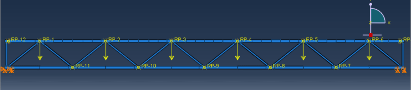
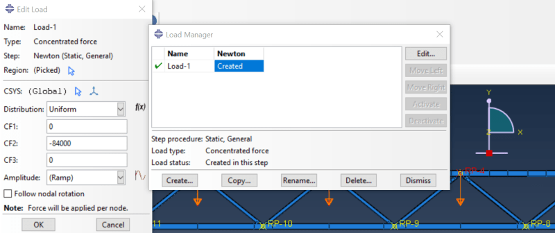
I am analysing an SHS steel truss, simply supported, with concentrated forces (in Newtons) applied in the top nodes. The loads are applied in reference points that are constrained, type coupling, to the section of the chord. All the top nodes have a boundary condition to prevent out of plane displacements.
Since what I want to achieve is the force-displacement curve of each of the truss nodes in the history output I requested the TF2 and U2 variables. The problem is after the analysis is completed, the RF2 for that node does not show any values. Apart from that, the displacement increases but after a while reaches a plateau which does not lead to the nodes deformation that was expected. I don't know if the problem is in the wais I defined the load or if it's the type of output I requested that is incorrect, but any help solving this problem is appreciated!
I will leave some pictures for a better understatement.
Thanks in advance.