Continue to Site

Eng-Tips is the largest engineering community on the Internet

Intelligent Work Forums for Engineering Professionals

  • Congratulations KootK on being selected by the Eng-Tips community for having the most helpful posts in the forums last week. Way to Go!

[ABAQUS] Apply distributed displacement vector from SSD analysis into Quasi-static cantilever beam 2

Status
Not open for further replies.

Frankie183

Mechanical
Jun 25, 2020
22
Good morning all!

From an modal analysis I analysed the resonance frequency of the first bending mode of a particular cantilever beam in ABAQUS CAE 2018.
At this particular frequency, my cantilever beam has a certain displacement field.
I want to export this displacement field towards a static beam element as a boundary condition.

I suppose it's somewhere in 'Create boundary condition', 'displacement & rotation'; where I can chose an uniform or user defined distribution. Is there a fast way to input a displacement vector field and distribute it over the elements or nodes?
Anyone of you'all who has a decent solution for this?

Thanks in advance!
 
Replies continue below

Recommended for you

When both meshes are equal, then it is simple.
Use the report option to export the displacements for each direction in seperate text file. Then use scripting or a good editor with a macro recorder to manipulte the files (see below) and then link the files with *Include into the input file of the static analysis.

Example:
a line in the file with displacement in x direction:
235, 4.2
(node number, disp value)

change that to
235, 1, 1, 4.2
 
Hi mustaine3,

Thanks a lot for responding that quick, appreciate it!
I tried your suggestions and proved very helpfull. I googled some around and found the Probe value function, which i was unaware of. that is perfect for writing my displacements as an output file. So that one is in the pocket.
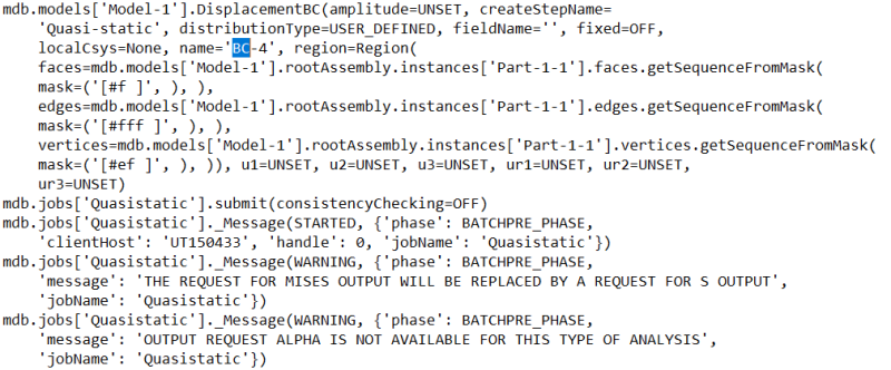
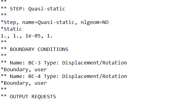
Only thing I'm struggling with is your recommendation on including the displacements in the file. I managed to open the JNL file (I prefer not to use the macro manager) and found the boundary condition location in the script (it's BC-4 in the attachment), but where am I now supposed to copy the displacements? couldn't really find the structure you proposed. Place it over the UNSET amplitude? and in what string? I'm not much of a programmer as you might have noticed haha ;)A small batch of the displacement values can be obtained in the other attached file.

Greetings,
Frank

Capture_mqblvj.png

--
1_kfirqf.png
 
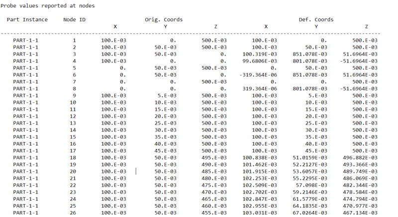
The file you've created contains the coordinates, not the displacements.
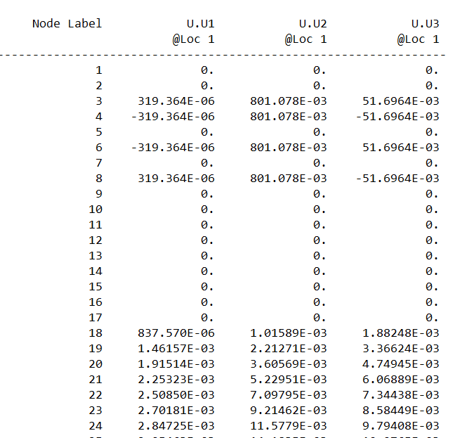
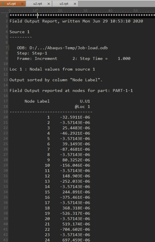
I would say Report -> Field Output is a better option to extract data to a file.

The file you have to put the displacements in is the input file (.inp). That's the file that is created by A/CAE when you submit a job. Here you have to add the displacements for each node when you ant to replicate the deformation. Afterwards you can submit the file with a DOS command: abaqus job=filename
As an alternative you can use the A/CAE Keyword Editor to add the the *Include keyword and then submit the job from within A/CAE.
 
Good morning,

Good, good, that makes more sense now indeed.
Before I perform too much unneccesary work; I extracted the output displacements as seen below:
Knipsel_wzdqtf.png


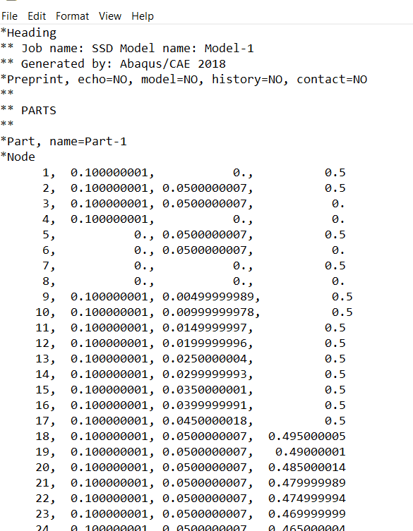
You wrote in your last comment that I have to 'add the displacements for each node'. Where exactly? Is that as a replacement for the nodes as this?-->
Knipsel1_dz3ttu.png


Or do I need to add them as boundary conditions as I thought previously?
Knipsel2_nuugdt.png


That it would look like:
** Name: BC-3 Type: Displacement/Rotation
*Boundary, user
1,1,1,0
1,2,2,0
1,3,3,0
2,1,1,0
2,2,2,0
2,3,3,0
3,1,1,319.364E-06
3,2,2,801.078e-03
3,3,3,51.6964e-03
etc.

If it is the last, is there a fast way or script available to do this? ;)

greetings,
Frank
 
You should export each displacement component in a separate file. It would look like this:
img-0161_hmzveq.png


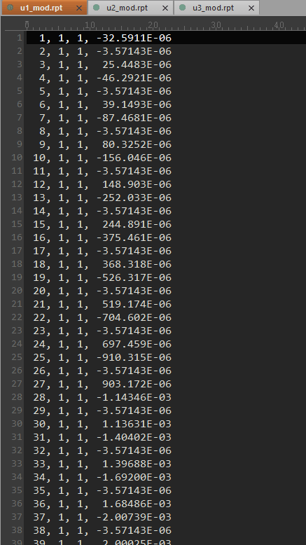
Then you edit this file to bring in a valid format for a boundary condition in each direction. It is up to you if you use scripting, a macro or a good editor with block/column editing. The result would look like this:
img-0162_ez2ky5.png


Then you take the input file of the analysis you want to do and edit the boundary option to refer to the files. This is done with the *Include-keyword.
img-0163_v1fz3d.png


Now you can submit this input file with a command line to Abaqus.

I would recommend that you define in A/CAE at the beginning of the first analysis, that the input file is written without parts and assemblies. This can be done with Model -> Edit Attributes. This makes it easier to work with the node number directly.

I've attached the files of my little example. It is a simple 3D beam. The first run is with an applied pressure load. Then I take those displacements and apply them again on the same model. The results are the same, as expected.
 
Good afternoon,

wow thanks a lot! I feel like I'm getting there. Only thing is that I am unable to open your version. Even with a conversion to the 2018 edition, it's somehow not working.
I managed to create the input files by a block editing tool (pretty useful, haven't heard of it before), so that should be allright.

However, if I create a new job with source the input file, where the input file contains the same input as yours:
*Boundary, user
*Include, Input = nodal_disp_u1_final.rpt
*Include, Input = nodal_disp_u2_final.rpt
*Include, Input = nodal_disp_u3_final.rpt

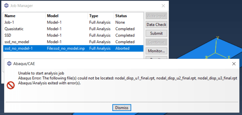
it gives the following error:
INP_capture_n6kxi9.png


then, if i change it to:
** Name: BC-3 Type: Displacement/Rotation
*Boundary, user
*Include, Input = E:\OosterveldFR\1.ABAQUS\SSD Cantilever beam\nodal_disp_u1_final.rpt
*Include, Input = E:\OosterveldFR\1.ABAQUS\SSD Cantilever beam\nodal_disp_u2_final.rpt
*Include, Input = E:\OosterveldFR\1.ABAQUS\SSD Cantilever beam\nodal_disp_u3_final.rpt

The file will be submitted, but eventually aborted.. Any insights on what I do wrong? I attached my files at the attachement.
 
I've created the CAE file with Abaqus 2020, so you can't open it with a older version than that. I've already expected that, so I've added the input files into the package.

Why are you using the "user" parameter at *Boundary? That option indicates that you want to use a user subroutine to control the boundary condition, which is not the case here. That's probably the reason why the analysis abort. Just use the *Boundary keyword without that option and it will probably work. See my example.

When you submit the second analysis with the included files, then Abaqus looks into the current work directory for the files, when there is only the file name referenced. You've worked around that by providing the full path to the files. That's fine. I just wanted to mention that. In A/CAE is an option to change the work dir. See File-> Set Work Dir...
 
Good afternoon,
Thanks, I can now indeed view your example as well, by using the input files.
I did remove the user parameter, from where abaqus can now see the included files, which is great!
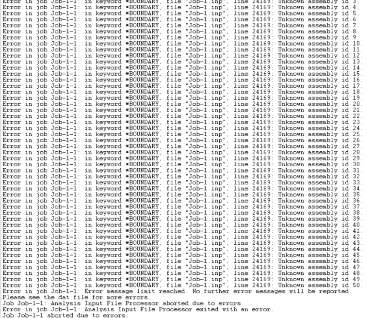
However, I thought I would've done it correctly now, if only abaqus would provide me with the next error. I'm reconsidering to build the model over again, but I fear that wouldn't help much. do you recognize this particular error?

Capture22_wh9pba.png
 
You don't have to built the model again. You just have to deactivate the part- and assembly structure in the initial input file. You can do that in A/CAE with Model -> Edit Attributes. Then every node will get a unique id. Otherwise (=default) A/CAE will generate the input file with a namespace for every part.
 
Status
Not open for further replies.

Part and Inventory Search

Sponsor