Eng-Tips is the largest engineering community on the Internet

Intelligent Work Forums for Engineering Professionals

  • Congratulations waross on being selected by the Tek-Tips community for having the most helpful posts in the forums last week. Way to Go!

Abaqus Concrete damaged plasticity - am I getting right behavior for a simple element?

Status
Not open for further replies.

StructuralCivilFEA

Civil/Environmental
Mar 2, 2020
12
0
0
NO
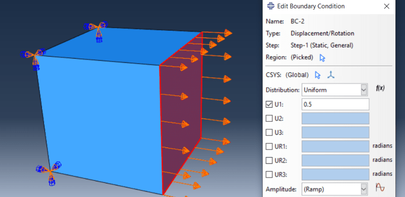
I am trying to see if my element has correct behavior in tension and compression. I have made a one element which is encastred at one side and elongated at the other.
CDP_mb5yj2.png

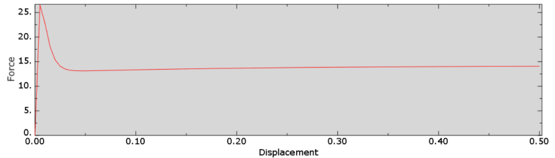
I get the following tension behavior:
Meridian_e9s4ga.png
.
Which seems okay if I compare too abaqus documentation on CDPM, besides that the force seems to increase slightly at the end.
Then I try in compression and get this:
Stress-strain_mtqef0.png

uniaxial_jqbjmo.png

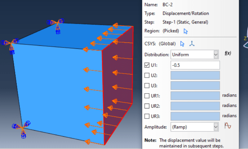
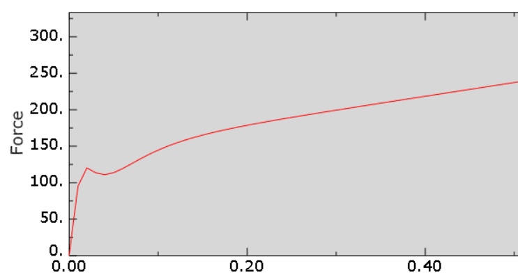
Why does the force keep increasing at the end? I have attached the CAE, any help would be appreciated as Ive been stuck for a while.
 
Replies continue below

Recommended for you

Can you also attach part of your input file with material definition (or whole .inp file) ?

Try with different boundary conditions - those used in the documentation example (Verification Guide —> Material Verification —> Mechanical Properties —> Concrete damaged plasticity) may be more appropriate. You can download the input file from there and simply replace material constants with your data.
 
I miss the FEA days. Approximating behavior and damage outcomes can be rewarding and fun(it also shows you just how simplified our general application of material models sometimes is). Years ago, I used the CDP model in an academic setting. I've forgotten the majority of the continuum mechanics it's built on because it's so esoteric. For validating the constitutive model, you should be studying the cyclic or loading/unloading behavior that occurs following onset of damage/elastic stiffness degradation. I would focus on the behavior of the compression and tension stress-strain curves first, rather than the force/displacement plots. We can only speculate on why the force/displacement plots behave like that, but at the end of the day, the material is behaving the way it was input.

As for the CDP, it's a rather complex constitutive model. The parameters for stress-strain behavior are unique for tension and compression. Also notice that damage doesn't equal plasticity and plasticity is different from compressive inelastic behavior. The CDP material is cool to play with, but it becomes very difficult to calibrate and justify advanced parameters. Don't get discouraged, but don't proceed without a full knowledge of the continuum mechanics ABAQUS is using. There are a lot resources out there you can use to study this. Also, search and post FEA stuff in the FEA forum. The general structures guys on here are always waiting to jump in and present their skepticism and laundry list of warnings/stories.

 
FEA way; I tried input file this way: but it gives me an error. Ive attached the steps I did, what is the right way to use an input file?
This is how it looks when I open it up:
CDP_hf3xfk.png

This is what I change to:
Meridian_oaxk67.png

This is the error message I get:
Stress-strain_nw3nbq.png

I ve attached the data I use, I use the data for 45 MPA. I have just manually added the material data.
 
The .inp file that can be downloaded from the documentation is a complete input file with all the data necessary for single element test analysis (not only material data). So you shouldn’t add it to your model. Instead edit this cdpse_c3d8r.inp file and replace material data with your own. Or import this file to CAE as new model and edit it there. The latter approach is not recommended though (CAE doesn’t support some keywords so it may not import the model completely).
 
Your end restraints look like a fixed support condition at the left. Is that intentional?

Here is a step by step video (Link)of a simple NLFEA beam analysis by a researcher from Univ of Toledo using Vector5. He also has a number of useful reports on the appropriate material models to use.
 
I had restrained displacement in all direction, which does not make it a tensile stress test. I removed displacement restriction in y and z direction and it worked, thank you for the help.
 
Status
Not open for further replies.
Back
Top