Eng-Tips is the largest engineering community on the Internet

Intelligent Work Forums for Engineering Professionals

  • Congratulations waross on being selected by the Eng-Tips community for having the most helpful posts in the forums last week. Way to Go!

abaqus isoparametric elements

Status
Not open for further replies.

Antonio22

Civil/Environmental
Apr 22, 2019
18
IT
Hi everyone, i have a problem with the stiffness matrix generated by Abaqus!
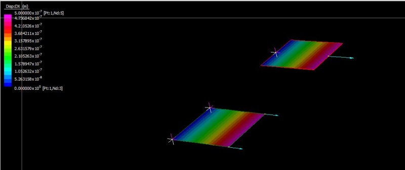
I have do a simple example: a plate in 2D dimension, subject to horizontal forces in the plane and stuck at one end. I resolved this problem in Wolfram Mathematica using isoparametric elements 4-node and i calculate the global stiffness matrix.
After i solved the same problem in Abaqus and I found the stiffness matrix, but this is different respect at the stiffness matrix that I calculate with Mathematica. Some elements are the same, but other are very different. I have try with CPS4 and CPS4R mesh in abaqus.

What's the possibile problem?? How i can use isoparametric elements in Abaqus?
 
Replies continue below

Recommended for you

The elements that you’ve mentioned are isoparametric by default in Abaqus. Make sure that both analyses (in Anaqus and in Mathematica) use the same settings and assumptions. Be aware that Abaqus is highly advanced solver and element formulation may differ a lot from the approach discussed in standard FEM literature - elements can be enhanced somehow.

Can you share your Mathematica code used for this analysis ? It will be easier to help.
 
OK first make sure you are getting the same results say for a 2D plane stress analysis on a single element. Just use one element and pull it on one edge while fixing the other.
 
Sorry i don't understant what do you mean by "pull it on one edge while fixing the other"
 
I consider a plate 2x2 (m) on abaqus with only one element and the stiffness matrix is already different from that on Mathematica!!
But i don't understand where is the possible error!!
 
How do you get the stiffness matrix from abaqus do you use *matrix generate or something - have in mind that this might give it in a non straight forward format.

If your results are the same (displacements), then that is the same so check your results first.

So just fix two nodes on one side of the element and apply a force on the other two, and make sure that you get the same results (displacements) in both, that is the easiest way to verify
 
I've already done this verification and displacement are different.
Recently using Abaqus, I will list the steps I have taken for the model in question:

I modeled the plate like a "2D planar,deformale, shell". Afetr I defined the material, the section (Solid, Homogeneus, with my thickness). I assegnement the section and I assembly with the command "Instances". After I defined the boundary conditions in the initial step, and the load in a new step (static). I created the mesh and I submited the "job".
For read the displacement i used the command Tools, Query, probe values.

It's correct?
 
Below is a simple test one can calculate by hand. 2D plane stress (2 DOF per node, X and Y, and 1 m x 1 m x 0.001 m single element), with a fixed edge and a membrane X-load on the opposite free edge.

The displacement should be Force/(EA/L) = 100 N/(200E9 N/m2*0.001 m2/1 m) = 5E-7 m (as seen below), that is what both truss and 2D plane stress elements give as shown below. Do the same thing with your script and you should get the same values, if not there is something wrong with that.

Capture_xr7y1l.jpg
 
That is not correct - sure an FEA software would be able to solve this :).

Attached is an input file that gives the answer as per analytical solution (x = (Force*L)/(E_mod* A_section) = 5E-7 m.

Finally the 8x8 plane stress (equal sides) local element stiffness matrix terms along x (1 direction here) should be for, k11, k33, k55, k77, equal to (E_mod*plate_thickness)/2.
(should mention that Poisson's, v = 0 in all the above discussions)

If we print out (*MATRIX GENERATE command) the stiffness matrix from abaqus (see below - just showing k11) then we can see that k11 is as expected here 1.000E8 N/m = (E_mod*plate_thickness)/2
(1,1, 1,1, 1.000000000000004e+08)

That is it for me now - good luck
 
 https://files.engineering.com/getfile.aspx?folder=bb451200-29fc-4020-8b14-2eff201664a7&file=Job-1.inp
Antonio22 - can you upload your Abaqus input file for which you get 1E-8 displacement.
 
Good afternoon, i found the error. I insered twice the value of the force! Now i obtained 5E-7 m!
Back to my case I had model in the same way my plate! I had already sheare the file mathematica where i calculated the stiffness matrix and the displacement. If you want i Will share also the file abaqus.
I really don't know where the mistake could be!
 
Hi! I found the error!! Thx you all! But I have another quest!

Is there a way to derive the connectivity matrix from abaqus?
 
According to the documentation, you can use *Matrix Generate keyword to extract the following matrices:
- stiffness
- mass
- viscous damping
- structural damping
- load

Unfortunately it appears that you can't make a request to output a connectivity matrix in Abaqus. But you may use Mesh --> Global Numbering Control to change element/node numbers or View --> Assembly Display Options to display element and/or node number labels.
 
Status
Not open for further replies.

Part and Inventory Search

Sponsor

Back
Top