DKEngineer
Student
- Apr 3, 2023
- 20
Hi,
I am trying to model an internal crack in a cylinder as seen on "Image_001". I am using the Abaqus contour integral method to model the crack in a 3D model. First I will verify the model by comparing the results of a penny shaped crack obtained in Abaqus to analytical solutions. Next I will model irregular shaped internal cracks. But the meshing seems to cause problems.
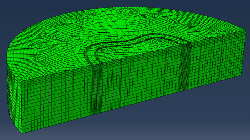
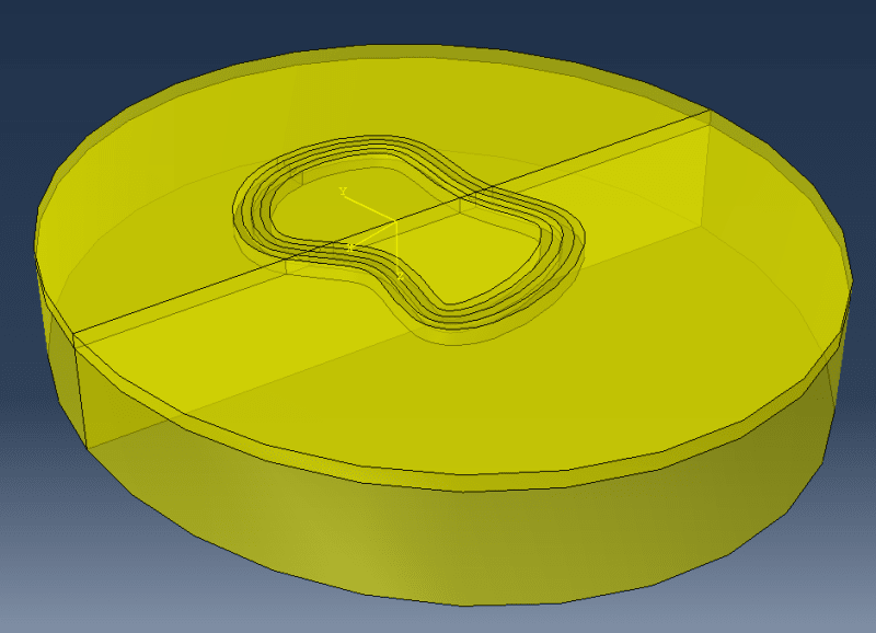
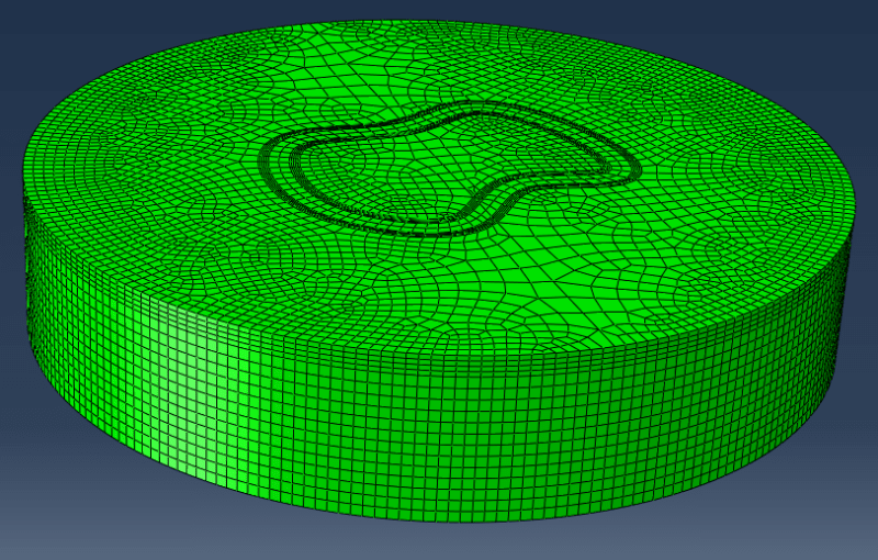
I am trying to partition the crack front with contours around it using shell sweep and then merge it into my solid cylinder. "Image_002", "Image_003" and "Image_004" shows that this is feasable for a cylinder cut in half (using double symmetry model). But as soon as I try to model the same penny-shaped crack in the cylinder using only symmetry in the crack plane, problems occur, which is seen in "Image_005" and "Image_006".
1) Why am I not able to mesh the cells around the crack front in this model?
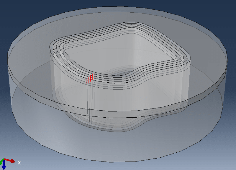
Next I will model an irregular shaped internal crack. The only method I could come up with was partitioning only vertical lines around the crack front through the whole cylinder as shown on "Image_009". Then I am using seeds on the lines marked with red to obtain mesh contours for the contour integral. But I like the partition used for the first model better.
2) Are there any suggestions for a meshing strategy for my problem?
Best regards
Image_001
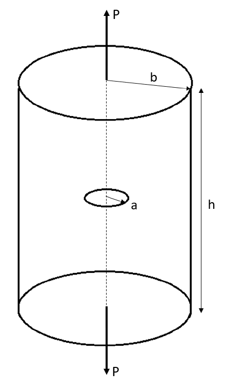
Image_002
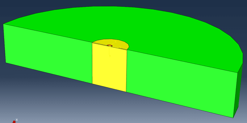
Image_003 (Red edge is crack front)
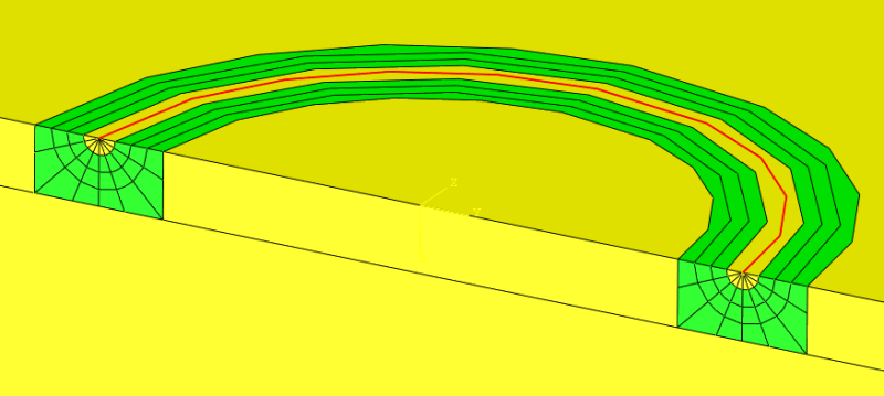
Image_004
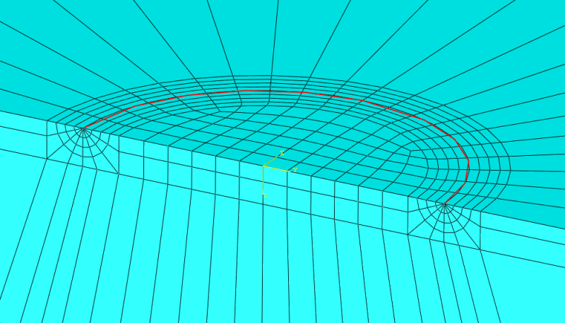
Image_005
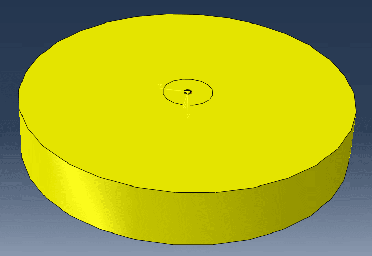
Image_006
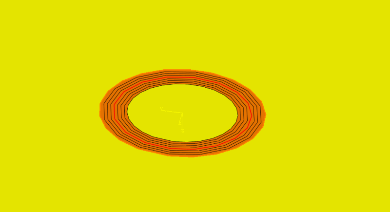
Image_007
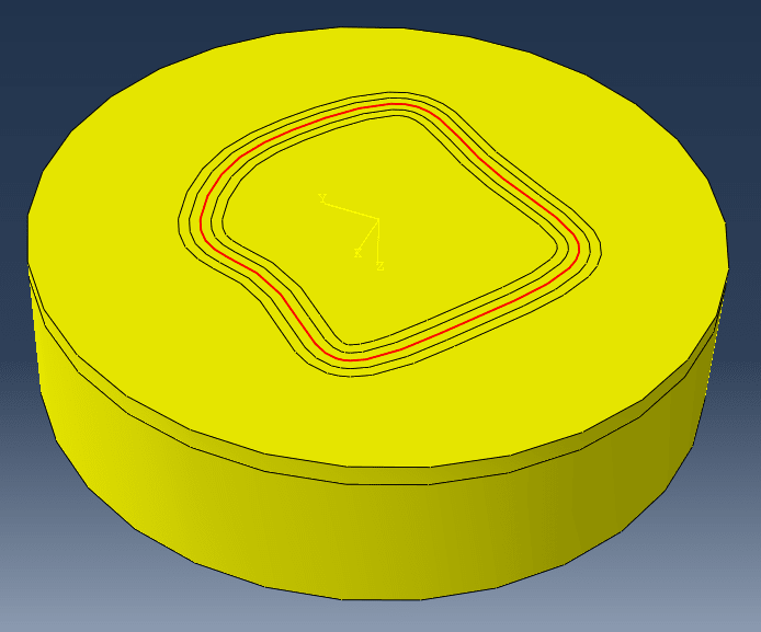
Image_008
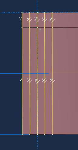
Image_009
I am trying to model an internal crack in a cylinder as seen on "Image_001". I am using the Abaqus contour integral method to model the crack in a 3D model. First I will verify the model by comparing the results of a penny shaped crack obtained in Abaqus to analytical solutions. Next I will model irregular shaped internal cracks. But the meshing seems to cause problems.
I am trying to partition the crack front with contours around it using shell sweep and then merge it into my solid cylinder. "Image_002", "Image_003" and "Image_004" shows that this is feasable for a cylinder cut in half (using double symmetry model). But as soon as I try to model the same penny-shaped crack in the cylinder using only symmetry in the crack plane, problems occur, which is seen in "Image_005" and "Image_006".
1) Why am I not able to mesh the cells around the crack front in this model?
Next I will model an irregular shaped internal crack. The only method I could come up with was partitioning only vertical lines around the crack front through the whole cylinder as shown on "Image_009". Then I am using seeds on the lines marked with red to obtain mesh contours for the contour integral. But I like the partition used for the first model better.
2) Are there any suggestions for a meshing strategy for my problem?
Best regards
Image_001

Image_002

Image_003 (Red edge is crack front)

Image_004

Image_005

Image_006

Image_007

Image_008

Image_009


