Martensite_Steel
Civil/Environmental
Hello there,
I'm learning Abaqus scripting with the Abaqus scripting reference guide. Not a beginner in Abaqus, but the scripting part is pretty new to me.
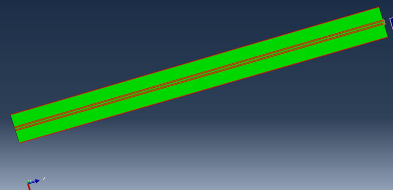
To apply local seeds to a flange, I'd like to select edges along the Z-direction of my part. It does work with the findAt command. However, since the partitions might change during parameter studies, I'd prefer to find all the edges via a getByBounding command and to put them in a set. I tried GetByBoundingCylinder, Sphere, Box.... Whatever I do, the set "seedsedge" always stays empty, although the reference guide clearly states, that these commands may be used to select edges for an edge array. When I apply a boundingsphere or cylinder in such a way, that it contains the whole part, I get all the edges inside. But thats not why I want. I just want the long edges in the set (see attached picture).

So, this might be an easy question for experienced scripters. However, I can't seem to find useful information on the web, so I hope for someone who could push me in the right direction.
Happy 3/14 everyone.
Here's the code:
from mesh import *
from part import *
from material import *
from section import *
from assembly import *
from step import *
from interaction import *
from load import *
from optimization import *
from job import *
from sketch import *
from visualization import *
from connectorBehavior import *
import math
m=mdb.models['Model-1']
p=m.parts
a=m.rootAssembly
l=2500.0
b=200.0
t_f=13.0
t_w=13.0
a=5.0
k=a/math.cos(math.pi/4)
h=200.0
h_w=h-2*t_f
Steel='S960'
### Residual
frf_plus=460.0
frf_minus=-120.0
frw_minus=-170.0
frw_plus=460.0
cp=t_w+2*(2**0.5)*a
Flange_res=t_f*(cp*frf_plus+(b-cp)*frf_minus)
cs=(-2*Flange_res+h_w*t_w*frw_minus)/(t_w*(frw_minus-frw_plus))
### Material
mdb.models['Model-1'].Material(name='S960')
mdb.models['Model-1'].materials['S960'].Density(table=((7.85e-09, ), ))
mdb.models['Model-1'].materials['S960'].Elastic(table=((210000.0, 0.3),
))
mdb.models['Model-1'].materials['S960'].Plastic(table=((960.0, 0.0), (
980.0, 0.055)))
mdb.models['Model-1'].Material(name='S690')
mdb.models['Model-1'].materials['S690'].Density(table=((7.85e-09, ), ))
mdb.models['Model-1'].materials['S690'].Elastic(table=((210000.0, 0.3),
))
mdb.models['Model-1'].materials['S690'].Plastic(table=((690.0, 0.0), (
790.0, 0.14)))
mdb.models['Model-1'].Material(name='S460')
mdb.models['Model-1'].materials['S460'].Density(table=((7.85e-09, ), ))
mdb.models['Model-1'].materials['S460'].Elastic(table=((210000.0, 0.3), ))
mdb.models['Model-1'].materials['S460'].Plastic(table=((460.0, 0.0), (525.0,
0.14)))
###Sections
mdb.models['Model-1'].HomogeneousSolidSection(material='S460', name='S460',
thickness=None)
mdb.models['Model-1'].HomogeneousSolidSection(material='S690', name='S690',
thickness=None)
mdb.models['Model-1'].HomogeneousSolidSection(material='S960', name='S960',
thickness=None)
### Parts
mdb.models['Model-1'].ConstrainedSketch(name='__profile__', sheetSize=200.0)
mdb.models['Model-1'].sketches['__profile__'].rectangle(point1=(0.0, 0.0), point2=(b, t_f))
mdb.models['Model-1'].Part(dimensionality=THREE_D, name='Flange', type=DEFORMABLE_BODY)
mdb.models['Model-1'].parts['Flange'].BaseSolidExtrude(depth=l, sketch=mdb.models['Model-1'].sketches['__profile__'])
del mdb.models['Model-1'].sketches['__profile__']
dtpoint1=mdb.models['Model-1'].parts['Flange'].DatumPointByOffset(point=mdb.models['Model-1'].parts['Flange'].InterestingPoint(mdb.models['Model-1'].parts['Flange'].edges.findAt((0.0, 0.0, l), ), MIDDLE), vector=(t_w/2, 0.0, 0.0))
dtpoint2=mdb.models['Model-1'].parts['Flange'].DatumPointByOffset(point=mdb.models['Model-1'].parts['Flange'].InterestingPoint(mdb.models['Model-1'].parts['Flange'].edges.findAt((0.0, 0.0, l), ), MIDDLE), vector=(-t_w/2, 0.0, 0.0))
dtpoint3=mdb.models['Model-1'].parts['Flange'].DatumPointByOffset(point=mdb.models['Model-1'].parts['Flange'].InterestingPoint(mdb.models['Model-1'].parts['Flange'].edges.findAt((0.0, 0.0, l), ), MIDDLE), vector=(t_w/2+k, 0.0, 0.0))
dtpoint4=mdb.models['Model-1'].parts['Flange'].DatumPointByOffset(point=mdb.models['Model-1'].parts['Flange'].InterestingPoint(mdb.models['Model-1'].parts['Flange'].edges.findAt((0.0, 0.0, l), ), MIDDLE), vector=(-t_w/2-k, 0.0, 0.0))
dtpoint1_id=dtpoint1.id
dtpoint2_id=dtpoint2.id
dtpoint3_id=dtpoint3.id
dtpoint4_id=dtpoint4.id
m.parts['Flange'].PartitionCellByPlanePointNormal(cells=m.parts['Flange'].cells.findAt(((0.0, t_f/2, 2*l/3), )), normal=m.parts['Flange'].edges.findAt((0.0, 0.0, l), ), point=mdb.models['Model-1'].parts['Flange'].datums[dtpoint3_id])
m.parts['Flange'].PartitionCellByPlanePointNormal(cells=m.parts['Flange'].cells.findAt(((0.0, t_f/2, l/2), )), normal=m.parts['Flange'].edges.findAt((t_f/2, 0.0, l), ), point=mdb.models['Model-1'].parts['Flange'].datums[dtpoint1_id])
m.parts['Flange'].PartitionCellByPlanePointNormal(cells=m.parts['Flange'].cells.findAt(((0.0, t_f/2, l/2), )), normal=m.parts['Flange'].edges.findAt((t_f/2, 0.0, l), ), point=mdb.models['Model-1'].parts['Flange'].datums[dtpoint2_id])
m.parts['Flange'].PartitionCellByPlanePointNormal(cells=m.parts['Flange'].cells.findAt(((0.0, t_f/2, l/2), )), normal=m.parts['Flange'].edges.findAt((t_f/2, 0.0, l), ), point=mdb.models['Model-1'].parts['Flange'].datums[dtpoint4_id])
edges = mdb.models['Model-1'].parts['Flange'].edges.getByBoundingCylinder((-b,0.0,l/2),(b,0.0,l/2),b)
mdb.models['Model-1'].parts['Flange'].Set(edges=edges, name='seedsedge')
I'm learning Abaqus scripting with the Abaqus scripting reference guide. Not a beginner in Abaqus, but the scripting part is pretty new to me.
To apply local seeds to a flange, I'd like to select edges along the Z-direction of my part. It does work with the findAt command. However, since the partitions might change during parameter studies, I'd prefer to find all the edges via a getByBounding command and to put them in a set. I tried GetByBoundingCylinder, Sphere, Box.... Whatever I do, the set "seedsedge" always stays empty, although the reference guide clearly states, that these commands may be used to select edges for an edge array. When I apply a boundingsphere or cylinder in such a way, that it contains the whole part, I get all the edges inside. But thats not why I want. I just want the long edges in the set (see attached picture).

So, this might be an easy question for experienced scripters. However, I can't seem to find useful information on the web, so I hope for someone who could push me in the right direction.
Happy 3/14 everyone.
Here's the code:
from mesh import *
from part import *
from material import *
from section import *
from assembly import *
from step import *
from interaction import *
from load import *
from optimization import *
from job import *
from sketch import *
from visualization import *
from connectorBehavior import *
import math
m=mdb.models['Model-1']
p=m.parts
a=m.rootAssembly
l=2500.0
b=200.0
t_f=13.0
t_w=13.0
a=5.0
k=a/math.cos(math.pi/4)
h=200.0
h_w=h-2*t_f
Steel='S960'
### Residual
frf_plus=460.0
frf_minus=-120.0
frw_minus=-170.0
frw_plus=460.0
cp=t_w+2*(2**0.5)*a
Flange_res=t_f*(cp*frf_plus+(b-cp)*frf_minus)
cs=(-2*Flange_res+h_w*t_w*frw_minus)/(t_w*(frw_minus-frw_plus))
### Material
mdb.models['Model-1'].Material(name='S960')
mdb.models['Model-1'].materials['S960'].Density(table=((7.85e-09, ), ))
mdb.models['Model-1'].materials['S960'].Elastic(table=((210000.0, 0.3),
))
mdb.models['Model-1'].materials['S960'].Plastic(table=((960.0, 0.0), (
980.0, 0.055)))
mdb.models['Model-1'].Material(name='S690')
mdb.models['Model-1'].materials['S690'].Density(table=((7.85e-09, ), ))
mdb.models['Model-1'].materials['S690'].Elastic(table=((210000.0, 0.3),
))
mdb.models['Model-1'].materials['S690'].Plastic(table=((690.0, 0.0), (
790.0, 0.14)))
mdb.models['Model-1'].Material(name='S460')
mdb.models['Model-1'].materials['S460'].Density(table=((7.85e-09, ), ))
mdb.models['Model-1'].materials['S460'].Elastic(table=((210000.0, 0.3), ))
mdb.models['Model-1'].materials['S460'].Plastic(table=((460.0, 0.0), (525.0,
0.14)))
###Sections
mdb.models['Model-1'].HomogeneousSolidSection(material='S460', name='S460',
thickness=None)
mdb.models['Model-1'].HomogeneousSolidSection(material='S690', name='S690',
thickness=None)
mdb.models['Model-1'].HomogeneousSolidSection(material='S960', name='S960',
thickness=None)
### Parts
mdb.models['Model-1'].ConstrainedSketch(name='__profile__', sheetSize=200.0)
mdb.models['Model-1'].sketches['__profile__'].rectangle(point1=(0.0, 0.0), point2=(b, t_f))
mdb.models['Model-1'].Part(dimensionality=THREE_D, name='Flange', type=DEFORMABLE_BODY)
mdb.models['Model-1'].parts['Flange'].BaseSolidExtrude(depth=l, sketch=mdb.models['Model-1'].sketches['__profile__'])
del mdb.models['Model-1'].sketches['__profile__']
dtpoint1=mdb.models['Model-1'].parts['Flange'].DatumPointByOffset(point=mdb.models['Model-1'].parts['Flange'].InterestingPoint(mdb.models['Model-1'].parts['Flange'].edges.findAt((0.0, 0.0, l), ), MIDDLE), vector=(t_w/2, 0.0, 0.0))
dtpoint2=mdb.models['Model-1'].parts['Flange'].DatumPointByOffset(point=mdb.models['Model-1'].parts['Flange'].InterestingPoint(mdb.models['Model-1'].parts['Flange'].edges.findAt((0.0, 0.0, l), ), MIDDLE), vector=(-t_w/2, 0.0, 0.0))
dtpoint3=mdb.models['Model-1'].parts['Flange'].DatumPointByOffset(point=mdb.models['Model-1'].parts['Flange'].InterestingPoint(mdb.models['Model-1'].parts['Flange'].edges.findAt((0.0, 0.0, l), ), MIDDLE), vector=(t_w/2+k, 0.0, 0.0))
dtpoint4=mdb.models['Model-1'].parts['Flange'].DatumPointByOffset(point=mdb.models['Model-1'].parts['Flange'].InterestingPoint(mdb.models['Model-1'].parts['Flange'].edges.findAt((0.0, 0.0, l), ), MIDDLE), vector=(-t_w/2-k, 0.0, 0.0))
dtpoint1_id=dtpoint1.id
dtpoint2_id=dtpoint2.id
dtpoint3_id=dtpoint3.id
dtpoint4_id=dtpoint4.id
m.parts['Flange'].PartitionCellByPlanePointNormal(cells=m.parts['Flange'].cells.findAt(((0.0, t_f/2, 2*l/3), )), normal=m.parts['Flange'].edges.findAt((0.0, 0.0, l), ), point=mdb.models['Model-1'].parts['Flange'].datums[dtpoint3_id])
m.parts['Flange'].PartitionCellByPlanePointNormal(cells=m.parts['Flange'].cells.findAt(((0.0, t_f/2, l/2), )), normal=m.parts['Flange'].edges.findAt((t_f/2, 0.0, l), ), point=mdb.models['Model-1'].parts['Flange'].datums[dtpoint1_id])
m.parts['Flange'].PartitionCellByPlanePointNormal(cells=m.parts['Flange'].cells.findAt(((0.0, t_f/2, l/2), )), normal=m.parts['Flange'].edges.findAt((t_f/2, 0.0, l), ), point=mdb.models['Model-1'].parts['Flange'].datums[dtpoint2_id])
m.parts['Flange'].PartitionCellByPlanePointNormal(cells=m.parts['Flange'].cells.findAt(((0.0, t_f/2, l/2), )), normal=m.parts['Flange'].edges.findAt((t_f/2, 0.0, l), ), point=mdb.models['Model-1'].parts['Flange'].datums[dtpoint4_id])
edges = mdb.models['Model-1'].parts['Flange'].edges.getByBoundingCylinder((-b,0.0,l/2),(b,0.0,l/2),b)
mdb.models['Model-1'].parts['Flange'].Set(edges=edges, name='seedsedge')
