Hello all,
First post; any help would be greatly appreciated (and apologies in advance if any improper thread etiquette).
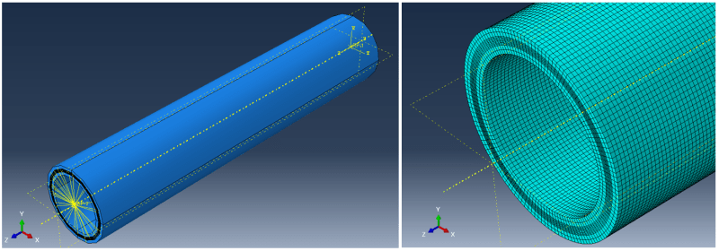
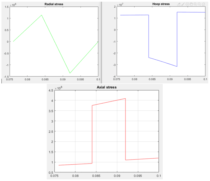
I have been stuck for a while with FEA of a thick-walled pipe (Ri=76mm; t=24mm) under pure bending. The pipe consists of different layers: isotropic and orthotropic. The pipe is a single 3D part layered by appropriate partitioning (i.e. layers assumed perfectly bonded), as I have done successfully in previous models of the same pipe under pressure and tension. I am interested in obtaining through-thickness cylindrical stresses such that I can validate the model against an analytical solution developed on MATLAB. FYI, I will eventually extend the model to include a coupled temp.-disp. step for thermomechanical analysis following validation of the pure bending case. So far I achieve good agreement for axial stresses through the thickness (XY data plotted through path). The (smaller) radial and hoop stresses are in the correct ball park, but more erratic and not correct.
As I understand is typical, I have created reference points at the centre of each pipe end onto which rotation is applied as a boundary condition in a static general step. The reference points are then coupled to the end faces via kinematic couplings.
I have tried countless combinations of boundary conditions, coupling types and DOFs, model geometries, step settings etc., but cannot achieve expected results, albeit I am not a million miles away. This leads me to believe I am fundamentally doing something, perhaps only slightly, wrong.
Some of what's been considered:
- Different combinations of boundary conditions/coupling DOFs (I have a 'best bet', which has not yet yielded an accurate solution; I would be interested in firstly hearing what others advise).
- Length of pipe affecting result: I have varied the pipe length. Above 500mm length or so, the axial stress correlates well with the analytical solution, suggesting this is not the culprit.
- Meshing: I am confident in creating well-structured and uniform pipe meshes (from experience). I am using C3D20R bricks, which I understand do not suffer from locking and hour glassing problems associated with linear bricks in bending. I have tried increasingly dense meshes (employing HPC), which does not appear to be noticeably improving the solution (within a practical limit). I recognise bending requires especially dense meshes, but surely not to the point that even HPC simulations will take forever to run?
- Nonlinearity: I have tried with/without NLGEOM=ON, different increment sizes etc.
I can of course provide further details of materials, input files etc., but I wonder at this stage if anyone can advise on just the general approach for applying bending rotation to a 3D pipe in a static general step. I would be grateful if you can consider aspects like NLGEOM, mesh density and so on. Perhaps I have been looking at this problem for too long and would appreciate some second opinions on the general approach to take.
Many thanks,
James
Mech. Eng.
First post; any help would be greatly appreciated (and apologies in advance if any improper thread etiquette).
I have been stuck for a while with FEA of a thick-walled pipe (Ri=76mm; t=24mm) under pure bending. The pipe consists of different layers: isotropic and orthotropic. The pipe is a single 3D part layered by appropriate partitioning (i.e. layers assumed perfectly bonded), as I have done successfully in previous models of the same pipe under pressure and tension. I am interested in obtaining through-thickness cylindrical stresses such that I can validate the model against an analytical solution developed on MATLAB. FYI, I will eventually extend the model to include a coupled temp.-disp. step for thermomechanical analysis following validation of the pure bending case. So far I achieve good agreement for axial stresses through the thickness (XY data plotted through path). The (smaller) radial and hoop stresses are in the correct ball park, but more erratic and not correct.
As I understand is typical, I have created reference points at the centre of each pipe end onto which rotation is applied as a boundary condition in a static general step. The reference points are then coupled to the end faces via kinematic couplings.
I have tried countless combinations of boundary conditions, coupling types and DOFs, model geometries, step settings etc., but cannot achieve expected results, albeit I am not a million miles away. This leads me to believe I am fundamentally doing something, perhaps only slightly, wrong.
Some of what's been considered:
- Different combinations of boundary conditions/coupling DOFs (I have a 'best bet', which has not yet yielded an accurate solution; I would be interested in firstly hearing what others advise).
- Length of pipe affecting result: I have varied the pipe length. Above 500mm length or so, the axial stress correlates well with the analytical solution, suggesting this is not the culprit.
- Meshing: I am confident in creating well-structured and uniform pipe meshes (from experience). I am using C3D20R bricks, which I understand do not suffer from locking and hour glassing problems associated with linear bricks in bending. I have tried increasingly dense meshes (employing HPC), which does not appear to be noticeably improving the solution (within a practical limit). I recognise bending requires especially dense meshes, but surely not to the point that even HPC simulations will take forever to run?
- Nonlinearity: I have tried with/without NLGEOM=ON, different increment sizes etc.
I can of course provide further details of materials, input files etc., but I wonder at this stage if anyone can advise on just the general approach for applying bending rotation to a 3D pipe in a static general step. I would be grateful if you can consider aspects like NLGEOM, mesh density and so on. Perhaps I have been looking at this problem for too long and would appreciate some second opinions on the general approach to take.
Many thanks,
James
Mech. Eng.
")