Continue to Site

Eng-Tips is the largest engineering community on the Internet

Intelligent Work Forums for Engineering Professionals

  • Congratulations IDS on being selected by the Eng-Tips community for having the most helpful posts in the forums last week. Way to Go!

Abaqus - thick-walled pipe bending

Status
Not open for further replies.

JamesCH

Mechanical
Feb 24, 2020
5
Hello all,

First post; any help would be greatly appreciated (and apologies in advance if any improper thread etiquette).

I have been stuck for a while with FEA of a thick-walled pipe (Ri=76mm; t=24mm) under pure bending. The pipe consists of different layers: isotropic and orthotropic. The pipe is a single 3D part layered by appropriate partitioning (i.e. layers assumed perfectly bonded), as I have done successfully in previous models of the same pipe under pressure and tension. I am interested in obtaining through-thickness cylindrical stresses such that I can validate the model against an analytical solution developed on MATLAB. FYI, I will eventually extend the model to include a coupled temp.-disp. step for thermomechanical analysis following validation of the pure bending case. So far I achieve good agreement for axial stresses through the thickness (XY data plotted through path). The (smaller) radial and hoop stresses are in the correct ball park, but more erratic and not correct.

As I understand is typical, I have created reference points at the centre of each pipe end onto which rotation is applied as a boundary condition in a static general step. The reference points are then coupled to the end faces via kinematic couplings.

I have tried countless combinations of boundary conditions, coupling types and DOFs, model geometries, step settings etc., but cannot achieve expected results, albeit I am not a million miles away. This leads me to believe I am fundamentally doing something, perhaps only slightly, wrong.

Some of what's been considered:

- Different combinations of boundary conditions/coupling DOFs (I have a 'best bet', which has not yet yielded an accurate solution; I would be interested in firstly hearing what others advise).

- Length of pipe affecting result: I have varied the pipe length. Above 500mm length or so, the axial stress correlates well with the analytical solution, suggesting this is not the culprit.

- Meshing: I am confident in creating well-structured and uniform pipe meshes (from experience). I am using C3D20R bricks, which I understand do not suffer from locking and hour glassing problems associated with linear bricks in bending. I have tried increasingly dense meshes (employing HPC), which does not appear to be noticeably improving the solution (within a practical limit). I recognise bending requires especially dense meshes, but surely not to the point that even HPC simulations will take forever to run?

- Nonlinearity: I have tried with/without NLGEOM=ON, different increment sizes etc.

I can of course provide further details of materials, input files etc., but I wonder at this stage if anyone can advise on just the general approach for applying bending rotation to a 3D pipe in a static general step. I would be grateful if you can consider aspects like NLGEOM, mesh density and so on. Perhaps I have been looking at this problem for too long and would appreciate some second opinions on the general approach to take.

Many thanks,

James
Mech. Eng.

 
Replies continue below

Recommended for you

Where do you measure the stresses ? Is the location where you measure them far enough from ends (boundary conditions regions) ? Are the material directions for orthotropic regions properly defined ?

I would also try with other types of elements - in this case primarily composite solids.

It would be best if you could attach a picture showing this model with boundary condition and mesh. And if you share the .cae or .inp file I will take a look at it and do some tests to find the reason of discrepancy.
 
Hi FEA way,

Many thanks for your response. I am measuring stresses through thickness directly in the middle. I have played around with pipe length, however no luck (unless I need to use an exceptionally long section with fine mesh, which does not seem consistent with fairly 'medium' lengths I've seen in various literature).

I am fairly confident the materials/partitions are correctly defined. As mentioned, I have effectively extended a model I used previously for pressure/tension, which agreed well with a MATLAB solution based on lamination theory.

I am especially interested in through-thickness stress distribution - following the case of pure bending I need to extend to include thermal stresses (specifically via surface temperatures/film coefficients generating through-thickness thermal gradient). As such, I am somewhat limited to the choice of elements? I had used C3D20RT in the previous pressure/tension model (with thermal load), for example.

I will collate and share images, .cae and .inp files shortly.
 
Meanwhile, can you say a bit more about your analytical calculations in Matlab ? Did you use some particular article or book for reference ?

How big is the difference ? Are the stresses too low or too high in Abaqus ?

I think that boundary conditions play the most important role here. But I would also play with various element formulations.
 
The analytical solution was developed on MATLAB in a study ( subscription required) and modified to the case of my pipe, here. The MATLAB solution is sound, and I can achieve reasonable correlation with FE for axial stress.

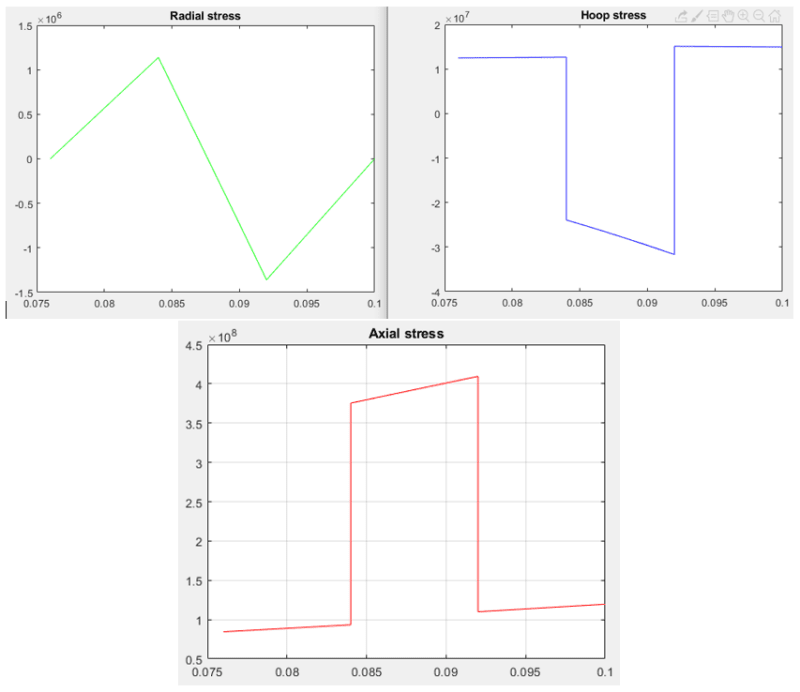
FE radial and hoop stresses are of the same order of magnitude as the MATLAB, however more erratic and not resembling the distribution. I would always expect the FE to vary somewhat but at least resemble the through-thickness distribution, if all is well and done.

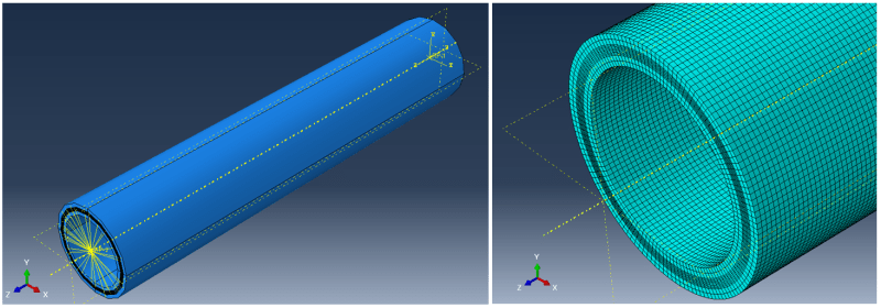
Please see general images of pipe model and mesh. Rotation is applied around x. I have also uploaded some target stresses obtained using the MATLAB.

Pipe_bending_fosycf.png

Validation_stresses_czoedz.png


Please find attached .inp file for the pipe. Note that I have played around with length, which hasn't improved the result thus far. Also note that the mesh is extremely dense to trim the input file. I have employed a supercomputer cluster to increase mesh densities to order of 10^6 (particularly with more elements through the thickness, which I understand is important for bending), however again this does not seem to noticeably change the results. Perhaps I must resign myself to having to run enormous simulations? (parametric variation and lot's of simulations was the aim here)

Please also note in the model:

- Boundary conditions/kinematic represent my 'best guess' thus far from literature (open source: Again, I have been playing with this.
- NLGEOM is on. I have tried with/without and varied increment. Perhaps there is a combination I missed.

Many thanks,
JCH

P.S. Is there a way to upload files >20MB here?
 
I had a look at your model. The boundary conditions seem correct. But to test different element types and mesh sizes I need the .cae file. Could you share it ? If it’s too big to attach here try File —> Compress MDB. Or provide URL for download from hosting service.

Just to make sure that you measure the stresses properly - you transform them to cylindrical coordinate system first, right ?
 
Thanks for looking into this. Here is the .cae file:
Yes, I have been transforming into a cylindrical csys for the stresses. I have also tried various combinations of RP boundary conditions/end couplings in cylindrical coordinates, e.g. to allow radial displacement of the ends. However, this does not alter the results significantly and the current constraints are required to keep ends plane upon rotated. Please note this is assumed to be a section of an infinitely long pipe in theory.
 
Based on the information I got from you and from your model’s files, I think that we can assume that there’s no error in the model. If the results mostly differ at layer interfaces and at free surfaces of the model then probably the discrepancy is caused by limitations of this approach where layers are modeled with homogenous section solid elements. Thus I think that you should focus on testing different element types. You can use composite section solids but stacked continuum shells are an option too. Shell elements may seem like a bad idea in this case where you are interested in through-thickness stress distribution but it’s very likely that they will actually prove better than solids.

For reference check the following benchmarks from the documentation:
- "Thick composite cylinder subjected to internal pressure"
- "Composite shells in cylindrical bending"
 
Hi,

I was dealing with a very similar problem a few weeks ago, in my case, I was studying the behaviour of an orthotropic pipe under internal pressure (I was following Xia's paper, which is mentioned in Menshykova's).

From my experience, I wrote the code in one go, as you probably know, hundreds of lines, almost impossible to be sure that everything was OK. Luckily for me, the paper came with a numerical example, so I went back and re-check the code, and I found a few small-silly-typo mistakes in some formulas. Eventually, I got the same results as in the paper.

When comparing with Abaqus, I got similar results, but not the same, the shear stress was slightly off, leaving me dissatisfied, but until today, I haven't found a solution (if there is a problem in first place). At this level of numerical and mathematical complexity, it is difficult to assert what method is right, ultimately, you need an anchor to reality (experimental data) to decide what method is better.

********

Looking at your model for 20 seconds, how do you apply the stacking sequence? Or is that only for 0 degree plies?

 
I definitely agree that experimental testing is the best way to dispel the doubts. However it’s also worth mentioning that if one seeks for agreement between numerical and analytical results then both approaches should follow the same assumptions. What I mean is that the numerical analysis shouldn’t account for effects that are ignored in analytical method (for example geometric nonlinearity).

The OP didn’t use composite section or composite layup features. He defined separate homogenous section for each CFRP ply and assigned different material orientations to these sections. That’s what, in my opinion, may cause the discrepancy.
 
Hi both,

Thanks for your input. I am looking into the use of alternative elements/approaches, namely a plane strain/generalized plane strain model. However, preliminary simulations for a homogeneous pipe appear to again be yielding inaccurate results (albeit correct ballpark, suggesting constraints are correctly applied etc.). As you suggest, I am beginning to think it is impossible to validate according to sound analytical theory which does not account for some 3D effect or non-zero interaction between stresses, likely due to inherent nature of the bending problem. I will investigate potential experimental data, although as you allude to I don't expect this to be easy to find!

Interesting you mention the Xia internal pressure paper. I too validated some models against their results as a foundation before introducing additional loads. I used both a shell approach and full 3D. I was able to replicate stresses closely. However, if I remember correctly there were non-zero stress distributions in shear planes expected to be zero according to theory, which were small and did not affect the overall result (e.g. in terms of Tsai-Hill coefficient) but I suppose further demonstrate inherent interaction in the model that is not expected to be there in a perfect formulation.

Thanks again :)
 
Can you say more about the plane strain model ? How do you load and constrain it ? A picture would be handy too.

In your case I would rather test 3D elements. Abaqus offers many types of them for various applications. The results obtained with each type of element may differ significant as shown by miscellaneous benchmarks, including those described in the documentation.
 
Status
Not open for further replies.

Part and Inventory Search

Sponsor