Eng-Tips is the largest engineering community on the Internet

Intelligent Work Forums for Engineering Professionals

ACB trips when the control power transfer from UPS A to UPS B 3

NickParker

Electrical
Sep 1, 2017
396
0
16
NL
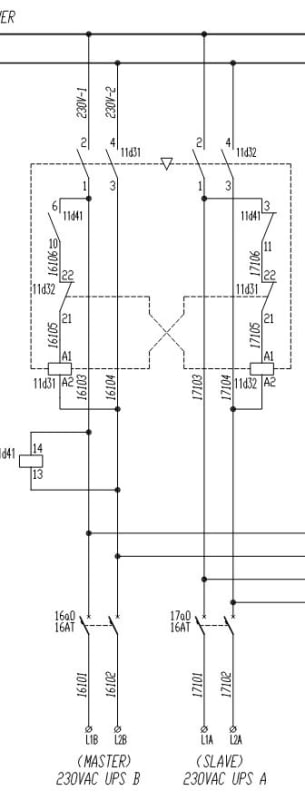
The control circuit is powered by two UPS units (UPS A and UPS B) with automatic transfer in case one fails. The motor feeder is supplied by an LV air circuit breaker (ACB), without a contactor. The ACB includes an undervoltage release (MN) and a shunt trip coil (MX).
Currently, when one of the UPS units fails, the ACB trips. However, I would like to prevent the ACB from tripping during the control power transfer between UPS A and UPS B. The control circuit diagram is attached for reference.
I would appreciate any suggestions!
 
 https://files.engineering.com/getfile.aspx?folder=b599eff2-99ea-4441-9cd0-80d1ce0ce9d1&file=B2-220416793-0010-BA001_Rev.006.pdf
Replies continue below

Recommended for you

Overkill.
If you are transferring between UPS units, your under-voltage release will trip during the transfer.
If you cascade the UPS units, Line-UPSA-UPSB-Load, then you will lose control power if UPSB fails.
Consider the case where you are running on UPSA and UPSA fails.
The loss of output from UPSA will initiate a transfer to UPSB, but at the same time will drop out your under-voltage release.
While the combination of a UPS and Under-voltage release seems contradictory and self defeating,I realize that a valid reason is possible.
If the application is so critical as to require two UPS units, it may be well to consider a battery system.


--------------------
Ohm's law
Not just a good idea;
It's the LAW!
 
I attempted to set a time delay for the undervoltage release (with a delay longer than the transition time between UPS A and UPS B), but the auxiliary relay KA1 still caused the breaker to shunt trip. One possible solution is to eliminate the shunt trip and rely solely on the undervoltage release with its built-in time delay.

waross said:
If the application is so critical as to require two UPS units, it may be well to consider a battery system.
Why would we need to consider a separate battery system? Isn't the UPS already equipped with a battery system? Are you suggesting that using the batteries would enable a seamless, bumpless transfer as it is DC power?
 
If I'm not mistaken, if a UPS fails, it will want to transfer from the inverter/rectifier to its static bypass. Maybe this is why the time delay on your UV release didn't work.

Mike
 
Actually the control circuit power to the MCC is fed from the UPS distribution board A and UPS distribution board B with automatic transfer happening in the MCC. (see the drawing below),
ups_gztvt9.jpg
 
Why would we need to consider a separate battery system? Isn't the UPS already equipped with a battery system? Are you suggesting that using the batteries would enable a seamless, bumpless transfer as it is DC power?
There are points of failure between the UPS batteries and the UPS output.
You may use two battery systems, tied together with diodes or one battery system with twin charging systems isolated with diodes.
Either will give a bumpless transfer.
Another possible solution that may be much easier and cheaper is to change the under-voltage release coil to a DC coil.
Use a local bridge rectifier to power the coil from the AC circuit. Add a capacitor to the DC side to carry over the transition period.


--------------------
Ohm's law
Not just a good idea;
It's the LAW!
 
@ Mr NickParker (Electrical)
I have the following opinion for your consideration.
1. The likely root cause is the DC supply from UPS A or B dropped to say < 50% during transfer. Attention: You may need a "Power meter" to capture this very short-time event. A simple digital multimeter may NOT capture it.
2. Observation: a) MX is an opening coil, NOT a shunt release. In most cases ACB can only installed with either a UV or a Shunt, but NOT both. b) the existing MN (UV release) is on 24Vdc.
3. The solution is to delay the MN from dropping out during UPS transfer.
Suggestion: Most ACB do have a simple external separate RC box for connection in parallel with the MN, preventing it from dropping out; for a short duration only. It is in their standard accessories, but is an optional item. Consult the OEM or read the catalog thoroughly. Attention: The local Sales office may NOT have the knowledge or has NO incentive to offer any advice or seek the factory for further information.
Che Kuan Yau (Singapore)


ACB with UV release - I expect the release to drop the ACB on sensing low voltage / no voltage at the output terminals of the ACB, in other words, on loss of voltage to the motor downstream.
If yes, it is incorrect to monitor UPS output using UV release of ACB, right!

R Raghunath
 
@ Mr. RRaghunath (Electrical)1 Oct 24 06:50
' ACB with UV release - I expect the release to drop the ACB on sensing low voltage / no voltage at the output terminals of the ACB, in other words, on loss of voltage to the motor downstream. If yes, it is incorrect to monitor UPS output using UV release of ACB, right!'[/color]
1. You are right in normal/usual case, where UV release is dependent on the power 690 Vac voltage level. It drops out may be as low as <45% and it picks up >85 % etc. But, the control circuit shows the MN (UV release) is on the 24 Vdc circuit. It is independent of the power 690Vac voltage level. I think the power 690Vac level is monitored by 1U ?. In this case, the MN , which is in series with 1U is controlled by 1U ?.
2. Mr NickParker is a learned seasoned engineer. He did NOT mentioned that there is a power 690Vac dip, but observed when there is a transfer of UPS.
3. BTW: a) An external RC connected across the MN to delay drop out could ? be helpful, irrespective of what causes the voltage dip.
b) a normal ACB under voltage release drops out say < 45% of rated voltage. I think this heavy voltage drop would be noticed by any experienced engineer.
Che Kuan Yau (Singapore)
 
Hi Mr. Che Kuan Yau,

Thank you for your reply,
1. The control power is of 230V AC fed by 230V AC UPS distribution boards
2. The ESD relay, K2 (SIL 3 rated) is of 24VDC - always energized - when deenergized - the contacts of K2 de-energises the undervoltage release (MN); which inturn trips the breaker (designed fail safe). (not sure the U1(time delay unit) which is in line with MN rectifies the voltage from 230V AC to 24V DC); think it should as it is a time delay unit.
3. There is no voltage dip in the 690V.
4. The other low capacity motors in the panel uses motor contactor combination (Type 2 coordination), which dont use any control power from UPS (control power using control transformer downstream of the MCCB)
5. It is only this motor (ACB fed) experiences this issue during transition of UPS A to UPS B.
 
RRaghunath said:
ACB with UV release - I expect the release to drop the ACB on sensing low voltage / no voltage at the output terminals of the ACB, in other words, on loss of voltage to the motor downstream.
If yes, it is incorrect to monitor UPS output using UV release of ACB, right!

Yes, that's how it should be, but here undervoltage release is solely used for Emergency shut down purposes (fail safe), not for monitoring the undervoltage . however since being a motor feeder, the breaker to be tripped on the 690V undervoltage or deadbus. Therefore, this feeder should have dedicated undervoltage relay which is missing.
 
no voltage at the output terminals of the ACB, in other words, on loss of voltage to the motor downstream.
The purpose of under-voltage release is a safety requirement to prvent a motor from starting automatically and unexpectedly when power is restored after an outage.
It will be connected to the input or supply side of the ACB.
Under-voltage release connected on the load side of an ACB will make it difficult impossible to close the breaker.
With the UVR on the load side of the breaker, the breaker will not close but will "trip free",that is it may cycle throgh the trip cycle without closing.

--------------------
Ohm's law
Not just a good idea;
It's the LAW!
 
'..The purpose of under-voltage release is a safety requirement to prvent a motor from starting automatically and unexpectedly when power is restored after an outage. It will be connected to the input or supply side of the ACB'.
I have different opinion.
1. In the usual case, a) when the voltage is up to say >85% UV coil voltage, the ACB can be closed, by the "closing coil". Attention: It does NOT close automatically by itself, even the spring is charged up.
b) when in closed state, it drops out at say <45% of coil voltage. Attention: It trips open automatically, without having to energize the "opening coil".
c) Upon power resumption after a blackout, the ACB would had been tripped opened Automatically but does NOT close back automatically. Unless a "on" signal is issued to the "closing coil".
d) It is NOT "... a safety requirement to prvent a motor from starting automatically and unexpectedly when power is restored after an outage".
2. BTW: In most ACB, the UV release operating voltage is say pick up >85% and drop out <45%, WITHOUT any provision for adjustment. For precise pick up/drop out voltage, is usually monitored by an external relay.
Che Kuan Yau (Singapore)
 
Your post is valid only for an ACB with an under-voltage release fitted, and then little confused.
A basic ACB DOES NOT DROP OUT ON THE LOSS OF SUPPLY VOLTAGE>
That is why under-voltage release is fitted when it is desired that the ACB drop out on loss of supply voltage.
It depends on the application whether or not an under-voltage trip is added or not..

--------------------
Ohm's law
Not just a good idea;
It's the LAW!
 
I wish to stress/clarify the following.
1. '..A basic ACB DOES NOT DROP OUT ON THE LOSS OF SUPPLY VOLTAGE. Agreed.
2. For an ACB with an under-voltage release fitted:
a) With ACB in open state, when the voltage across the UV say > 85% rated voltage; the UV coil picks up. But, Note: The ACB remained in open state. It does NOT close automatically.
Note: 1. there is NO danger to the load, as it remained in the Open state.
Unlike a Contactor where it Closes automatically, when the voltage say > 85% is applied.
2. To close it, a "on" signal to energize the Closing coil is needed.
3. the UV coil volage rating (e.g. 24 Vac) may NOT be the same as the Power supply voltage (e.g. 690 Vac). In this case, a step-down transformer or an external voltage relay with pick-up/drop-out adjustment would be needed.
3. When the ACB is in Closed state:
a) When power failed, ACB trips open automatically,
b) When power resumes, ACB remained in open state.
Note: There is NO danger that the motor may start inadvertently.
Che Kuan Yau (Singapore)
 
I agree with you, Mr Che.
Another point;
The under-voltage release coil must be energized before the breaker may be closed.
The ACBs that I worked on, if a close signal was given, that is, the close coil was energized, the charging spring would discharge but the contacts would not move and would remain in the open position.
The spring would have to be recharged, automatically or manually, before the ACB would respond to another close signal.
An interesting note.
I worked on a 31 cubicle switch-gear lineup.
About 25 cubicles were populated with ACBs.
There was one charging motor.
When a breaker was to be closed, the motor would be installed (It was quick and easy, just two wing-nuts held it in place).
The breaker would be charged if needed and then closed. The closing spring would be re-charged ready for another close if needed.
The charging motor would be removed and taken back to the shop.

--------------------
Ohm's law
Not just a good idea;
It's the LAW!
 
'...There was one charging motor. When a breaker was to be closed, the motor would be installed (It was quick and easy, just two wing-nuts held it in place). The breaker would be charged if needed and then closed. The closing spring would be re-charged ready for another close if needed. The charging motor would be removed and taken back to the shop'.
1. My experience is that this is NOT the usual practice for LV. It is NOT practical to bring along the (one and only one) spring charging motor from the shop to close any breaker. Noted: breaker switching is usually of rather low frequency.
2. All LV breakers are always designed with "manual" spring charging provision; even friendly to females. BTW: charging motor is always as an optional item.
Che Kuan Yau (Singapore)
 
waross said:
Use a local bridge rectifier to power the coil from the AC circuit. Add a capacitor to the DC side to carry over the transition period.

I’m considering using this type of capacitor trip device or an off-delay timer to maintain the transition period. However, since this is a motor circuit, it may also delay the trip on actual fault. The ACB has a Micrologic electronic trip unit; my question is whether the Micrologic unit directly trips the ACB or activates the shunt trip.
 
@ Mr NickParker (Electrical)(OP)
I have the following opinion for your consideration.
Check the ACB catalog, as it may defers between OEMs.
1. The time-delay device (from the same OEM) as the UV release may be adjustable say 0.5-.. s etc. It delays only the UV from dropping out. It does NOT delay the trip on actual fault. See 2. below.
2. When a fault is detected by the Micrologic unit, it trips the trip bar; which is independent of the UV or shunt release.
BTW: Any basic ACB with Micrologic unit may not be installed with a UV or shunt release.
Che Kuan Yau (Singapore)
 
Back
Top