Eng-Tips is the largest engineering community on the Internet

Intelligent Work Forums for Engineering Professionals

  • Congratulations waross on being selected by the Tek-Tips community for having the most helpful posts in the forums last week. Way to Go!

ACI 17.4.2.9 Anchorage Reinforcement Within PT Slab (Tension) 1

Status
Not open for further replies.

Shanman_

Structural
Oct 25, 2017
18
0
0
US
Hi All,

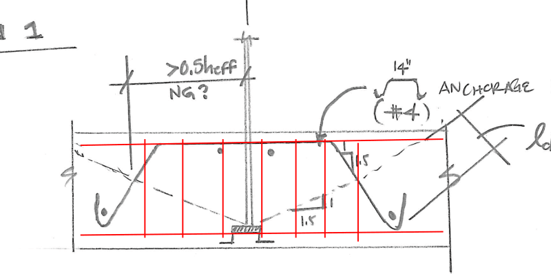
Would appreciate input on the attached detail sketches. We have a job going through DSA (Division of the State Architect here in CA - for schools) where a detail we routinely use for anchorage was rejected due to the distance from centerline of anchor to the intersection of the anchorage reinforcement and the theoretical breakout plane being larger than 50% of h(effective) - see ACI 17.4.2.9 commentary.

After going through examples of details from other Structural firms and even through Simpson's Shallow Anchor Technical Blog, Technical Paper (w/ associated load testing) - we are feeling pretty comfortable that either detail 1 or 2 in the attached should be sufficient.

I would like to invite any thoughts/comments/concerns with either option or for anyone to share any resources they have on what they feel the right solution is. Keep in mind the force is in the order of 60kips into a 12" PT slab-on-grade. Ignoring edge conditions, this detail usually requires two of these "mustache bars" (as I call them) each way to restrain the breakout cone. We then check punching shear on an outer critical perimeter at the extremities of the reinforcing bars to ensure no failures would occur in that plane.

Thanks!

KS
 
 https://files.engineering.com/getfile.aspx?folder=8e738e01-54a1-4d4e-aa7a-f2b55f299d19&file=scan20210719182548044226.pdf
Replies continue below

Recommended for you

It is interesting that Simpson's example sums the contribution of the concrete breakout and anchor reinforcement while the technical paper does not give specific guidance on how this should be accomplished. It only reports that the tests and FEA show that there is some contribution.
 
sums the contribution of the concrete breakout and anchor reinforcement

With ACI it is expressly one or the other, by utilising anchor reinforcement you are expressly accepting that the concrete has already failed (or is in the process of failing), and the reinforcement is taking over the load carrying duties.

That is why I think the 0.5 h_eff limit exists as the concrete mechanism spreads from the anchor as the failure occurs, so the reinforcement needs to be close enough to take over as the primary load carrying mechanism.

Now the way I would treat this conceptually is to have a stirrup cage with longitudinal bars top and bottom of the slab, that way there is a strut and tie load path within the stirrups even without the full reinforcement development either side of the breakout surface.

image_ooesnm.png


@pvchabot - Indeed, Simpson appears to be going beyond the letter of the code solely with the backing provided by their own test data. In my case, I would size the anchorage reinforcing bars to resist 100% of the uplift load. Any contribution provided by the concrete would be a cherry on top for me. I think this more closely follows ACI 17.4.2.9's wording on using anchor reinforcement instead of concrete breakout.

@Agent666 - I think knowing in your heart that the concrete will still give a significant contribution to precluding a breakout failure would just help most of us sleep at night. I'm in agreement that there certainly is some logic to the 0.5h_eff limit based on how the stress projects away from the end of the anchor and engages the reinforcement. Lastly, the stirrup solution is routine for two-way shear (punching) and is an option. I'm concerned that doesn't follow the letter of the code either, though. 17.4.2.9 would not be met with stirrups given the geometry.
 
I fail to see the difference in applying the same load to the underside of the slab with a stirrup cage, or partial depth in the stirrup cage as you have it provided there is a strut and tie solution. It won't comply word for word directly with chapter 17, but this is where your judgement as an engineer comes in and you provide an equally acceptable alternative.

If going with the single bar as per your original details, then I'd say you should be complying with the 0.5h_eff limits and the anchorage either side of the breakout which neither strictly comply with.

 
@Teguchi - Indeed the code does state under 17.4.2.9 that anchor reinforcement must be developed on both sides of the breakout surface. For detail 1 on that first attachment I put in my original post it had Ldh below and a full Ld above (measured across all straight segments of rebar). The shape doesn't match the commentary of 17.4.2.9 exactly but then again it never does since nobody uses downward facing hairpins like it is shown.

However, in looking at the testing done by Simpson as shown in their Technical Paper I linked (funded through SEAONC Special Projects Committee- Structural Engineers Association of Northern California) they used the geometry I show in my 2nd detail. Although even more unorthodox in terms of developing Ld/Ldh on either side of the breakout surface, their load testing confirms that it is an acceptable geometry for precluding breakout through anchorage reinforcement. It also confirms that concrete breakout strength's contribution to total peak load capacity is not zero. In fact, it plays a significant role. This and many other interesting things are covered in their report.

I am thankful that SEAONC funded that project as section 17.4.2.9 is not explicit enough and many firms are using anchorage details similar to ours with no concrete backing by the code. (ha, pun intended)
Hopefully someone takes it a step further and gets something codified soon for anchorage reinforcement in shallow slabs.
 
Status
Not open for further replies.
Back
Top