Continue to Site

Eng-Tips is the largest engineering community on the Internet

Intelligent Work Forums for Engineering Professionals

  • Congratulations KootK on being selected by the Eng-Tips community for having the most helpful posts in the forums last week. Way to Go!

Adding a VFD for the purpose of preventing cavitation and low suction pressure/NPSHA

Status
Not open for further replies.

Fooooks

Mechanical
Sep 15, 2016
48
Hello all,
We are currently having two issues with our existing PD pumps that we use to unload rail cars. They are cavitating and aerating due to the varying product levels in the rail cars. We typically unload from multiple cars simultaneously, and this makes it difficult for our operators to determine when suction pressure gets too low (outside of a pressure gauge on the suction of the pump) or that a tank car is empty and they are pulling air into the pump. Operators will run the pump full speed (connected to an existing VFD for speed control) and slow it down only when the pump starts to vibrate excessively or they hear the noises associated with cavitation/aeration in the pump.

Design
I will be adding a positive displacement pump for the purpose of unloading vegetable oil from these rail cars. A VFD will be added that will be tied into a suction pressure transmitter. The vegetable oil has an assumed vapor pressure of 0.02 psia, S.G of 0.9, and a viscosity ranging from an estimated 75-300 cst depending on temperature. The pump we are using has an NPSHR at design speed of 8.6 ft. After running some calculations, the NPIP (Net positive inlet pressure) for the pump would be approximately -10 psig. The VFD will theoretically be tied to a suction pressure transmitter so as to decrease the motor speed when the suction pressure gets too low. This would theoretically protect the pump from cavitating by increasing NPSHA. What do you all think of this design? The only problem I am having is how to protect the pump from aerating when rail cars empty while the pump is still running. We would want to completely pump all of the product from the rail cars and suction line if possible.

Cavitation Questions
After considering this system, it made me dive deeper into the NPSHA > NPSHR rule. Everywhere I have read said this is to prevent cavitation and "starving" the pump. But if the vegetable oil has a vapor pressure of approximately 0.02 psia, does this mean that when the NPSHA drops below NPSHR, there is essentially a complete vacuum at the inlet of the pump, causing flashing of a vegetable oil?

I can see this clearly when thinking about water or a hydrocarbon, but it seems strange that vegetable oil would be able to flash in a similar fashion. Can someone explain what is actually happening locally to the vegetable oil? Is the vacuum really flashing the oil if there is vapor space in the pipeline or the pump, assuming no air entered the system?

I am hoping to get some insight which may help the design.

Thanks!
 
Replies continue below

Recommended for you

Unless the rail cars are 9 meters below the pump, the oil will not reach its vapour point.

So, exactly how low is the lowest rail car?
 
Agreed, vegetable oil would have next to no volatiles so the concept of NPSHr, NPSHa, cavitation has no meaning in this context. But one would try to avoid air from getting into the pump suction to avoid loss of priming / overheating in the pump casing.

Set the low range pressure transmitter to say 1 or 2inches of oil column to auto stop the pump. Dont see why you need a VFD here.
 
Cavitation does not require that any volatile component be in the fluid. Volatiles just make cavitation occur at a higher absolute pressure, and therefore more likely. In fact, having no vapor in the bubbles makes the collapsing bubbles more damaging.
 
Wouldnt call myself a pump expert, so here is the abstract from the author of chapter 10 in Perry on cavitation in pumps (page 10-23 in the 7th edn)
----------------------------------
Suction Limitations of a Pump
Whenever the pressure in a liquid drops below the vapor pressure corresponding to its temperature,
the liquid will vaporize. When this happens within an operating pump, the vapor bubbles will be carried along to a point of higher pressure, where they suddenly collapse. This phenomenon is known as cavitation.
Cavitation in a pump should be avoided, as it is accompanied by metal removal, vibration, reduced flow, loss in efficiency, and noise.
When the absolute suction pressure is low, cavitation may occur inthe pump inlet and damage result in the pump suction and on the impeller vanes near the inlet edges. To avoid this phenomenon, it is
necessary to maintain a required net positive suction head (NPSH)R, which is the equivalent total head of liquid at the pump centerline less the vapor pressure p. Each pump manufacturer publishes
curves relating (NPSH)R to capacity and speed for each pump.
-------------------------------------

Other literature on the net tell of the same requirement for the saturation vapor pressure of the liquid to be less than the local operating pressure at the pump inlet or impeller surfaces for cavitation damage to occur further downstream where fluid pressure increases. Obviously, the quantity of the vapor released at the low pressure suction should also be sufficient to show up as mechanical vibration, erosion and loss of hydraulic performance.

Non condensible gas entrainment into the pump can also cause mechanical damage to bearings. seals, overheating, loss of performance etc, but this is not fluid cavitation related.

 
Check that each of these railcar tanks has a vortex breaker fitted into the discharge nozzle leading to the common pump suction, else you'll draw in air prematurely.
 
Yes, and when the fluid has zero vapor pressure cavitation will occur at zero absolute pressure. It is the momentum of the fluid in turbulence that causes the low pressure which leads to cavitation. Fluid vapor pressure is not necessary for cavitation to occur, but it helps.

When the momentum forces in the fluid exceed the pressure (and the van der Waals) forces holding the fluid together, cavitation occurs.
 
Bimr and Hpost,
The railcars are vented to atmosphere. However, when flowing into the pump at approximately 1700 GPM, the friction losses in the suction pipe bring the NPSH available to approximately 10.4 ft. When increasing the flow rate to 1800 GPM (which the pump is rated for), the NPSH available is 7.7, which is BELOW the NPSHr of the pump. The lowest level in the rail car would be approximately 2 feet below center line of pump suction.

Georgeverghese,
I believe we want the capability of speeding and slowing down the pump regardless, and so a VFD is what we use for most of our pump to accomplish this. Looking above, at high flow rates our NPSHa is lower than NPSHr, so why would cavitation have no meaning in this context? We will also check to see if the rail cars have a vortex breaker, but we have multiple customers and I doubt they all would. I agree the air would cause an issue, and am looking at other ways to avoid getting air in the system on our end and not rely on the customer.

Compositepro,
So since the NPSHa is less than NPSHr in the calculations I am running, it is safe to assume it is almost a complete vacuum in the suction piping and therefore the absolute pressure is lower than the 0.02 psia vapor pressure of the oil? Is the cavitation of the oil the same phenomenon that is occurring with other liquids, that the liquid is boiling and vaporizing and the vapor bubbles are collapsing at higher pressures?

Thanks

 
Finally got round to answering this using a proper key pad instead of a phone....

Still don't have a good idea of your system but I assume it's some sort of header pipe with multiple tanker cars connected and then a pump either mid point or at the end of the siding??

Your product is particularly gloopy at 75 to 300 CP so I'm not surprised you're A) using a PD pump (what type?) and B) getting some high frictional losses.

What you have tells me your header is undersized for your product or that the coldest conditions need longer to unload.

Unloading rail cars is an interesting transient problem as not all rail cars will unload equally unless you have a massive header. Generally those closest to the pump will finish before any others so as you are running sub atmospheric pressure you should monitor the rail cars starting at the one which empties first then isolate it just as it empties otherwise you'll start pulling in air.

To answer your other questions though - NPSHR is not about cavitation. NPSHR is defined as the inlet head at which the differential pressure at a series of constant flows decreases by 3%. Cavitation can start to occur earlier than that or not at all, but onset of cavitation is is difficult to measure so the pump vendors go for the 3% rule as this can be measured quite accurately. The head is always given at the centre line of pump or sometimes centre or face of inlet flange. Within the pump itself the pressure or head might fall still further which is when in your case you could get to very low pressures and have the vegetable oil start to vapourise and then collapse. PD pumps, especially piston or reciprocating units also include acceleration head due to the sudden acceleration of fluid into the piston.

So yes, setting a pressure limit and then slowing the pump down to reduce your frictional losses would be one way of controlling flow to avoid cavitation. A larger header or perhaps heating the fluid would also help. Some train off loading systems use a buried tank with a vent to higher than the rail car highest head to flow into under gravity then pump out from there to provide a buffer volume and then control flow on level in the tank, but that's a bit more involved. Having two or more smaller pumps in parallel is also used to step change flow rates to allow for the different flow rate you get, especially towards the end of the unloading time.

Hope this helps.


Remember - More details = better answers
Also: If you get a response it's polite to respond to it.
 
LittleInch,
Yes, the system has multiple rail cars connected to a header pipe and the pump at the end. We currently use sliding vane Blackmer pumps and rotary gear Viking pumps.

I agree the header is undersized for the product.

Our operations department should be monitoring the rails cars, isolating them as they empty; but this is not the case at all times. It can be several minutes that the pump is pullingair from an empty rail car. During this time, vibration in the pipeline begins to increase when the pump "burps" large pockets of air. We are set up with vibration switches which will also slow the pump down in this scenario.

Thank you for the NPSHR information, I do remember reading that the Hydraulic Institute establishes the NPSHR at the first indication of any of the following (given constant differential pressure and speed): Cavitation noise is heard, 5% reduction in capacity, 5% reduction in power.

I also read from various sources that cavitation occurs when NPSHA < NPSHR, which is where my confusion was. I assume this wording can vary from source to source.

Thank you for the suggestions. It is possible to increase the suction header, but it would take a lot of effort as our pipe rack is old, filled, and difficult to reach for new installations. We may have the capability of adding steam tracing to the line.
 
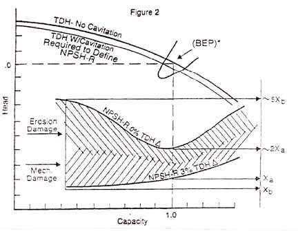
Cavitation can occur above NPSHR, sometimes a lot more ( 3-10 ft).

For centrifugal pumps this sort of curve isn't uncommon.

NPSH_bxooxz.jpg


There are level transmitters which hook onto the open lids of rail cars so if you fitted one to the car which always empties first then at least you have some sort of warning / alarm.

There are also mechanical devices which can shut off flow when no liquid is present (like a condensate steam trap) which might be able to be used in each offloading connection?

Remember - More details = better answers
Also: If you get a response it's polite to respond to it.
 
I have never seen a curve like that, thanks.

I'll ask some of the vendors we have for a device that would shut with no liquid. I think that would work very well in this situation if they are not too costly.
 
Pls also note that NPSHr is a also function of the fluid viscosity - see Perry. Many vendors dont bother to correct their NPSHr for viscosity effects even when they know the fluid being pumped is not the same as the test fluid used for the factory determined NPSHr.

Vortex breakers should be installed, else you'll have railcars that are not completely emptied. Agree, if you have an undersized suction header, you'd have the tanks furthest downstream emptying earlier than the ones further upstream of the pump. A VFD on the pump to slow the pump down toward the end of this unloading operation may then help to "equalise" the tank levels somewhat since the suction header flows are lower and friction dp is less. I wouldnt get too hung up over NPSHr requirements for vegetable oil with a vapor pressure of 0.02psia. This is only applicable when fluids contain an amount of volatiles sufficent to affect pump performance.
 
Unequal flow amongst these railcars connected through a long suction line may be much less of a problem if you were to run this entire operation in several batches, with not more than say 2 adjacent railcars per batch.

Strictly speaking, you should get the pump vendor to run an NPSHr test with the vegetable oil as the test fluid if you were to take these values seriously.
 
Georgeverghese,
I will certainly reach out to the pump vendor to see if they have NPSHr tests with the product or if they could run them for us. Even if I do not get hung up over NPSHr with a vapor pressure of 0.02 psia, I would still see reductions in flow and power, even if not through the development of vapor bubbles. At least this is my understanding after reading previous posts on this page.

Thanks for all the responses.
 
Fooooks

You need to forget about the low vapour pressure of the oil. You ate already getting credit for that in the NPSHA calculation. NPSHR is measured at the inlet flange. Within the pump at a microscopic level pressure can fall even lower and yes the oil will create small bubbles which then promptly collapse very quickly which is cavitation.

Most of your issue in bubbles and vibration sound like large air inlet issues to me caused by low / no liquid level in the rail cars.

Remember - More details = better answers
Also: If you get a response it's polite to respond to it.
 
Most of your issue in bubbles and vibration sound like large air inlet issues to me caused by low / no liquid level in the rail cars.

I would agree with the Little Inch's comment. Air getting in the pump is not the same as cavitation but the impact is similar and is often confused to be cavitation. This is very common in HVAC cooling tower pumps which SOUND like they are cavitating because of the entrained air. The approach to correcting the problem is however quite different. Your approach to lowering the speed using a VFD is correct. What speed are you running the PD pump under normal operation? If the friction loss in the suction line is too high why not run the pump on a slower speed. It may take longer to pump but does that really matter. Read the excerpt from a seminar below

CONSIDERATIONS FOR SELECTING AND APPLYING COOLING TOWER PUMPS: DEALING WITH HIGHLY AERATED WATER
Presented by Mr. William Armstrong, President of Fluid Handling.
Sponsored by Fluid Handling
Mr. Armstrong comes to us with unique pumping experiences that are very rarely discussed. It involves special considerations when handling highly aerated water, which is a consideration with every cooling tower. Nearly every serious pumping problem out there often involves cooling tower water and the problem always involves air. What air does is come out of solution at the lowest pressure point in the system, which is at the pump suction connection. The result is a phenomenon that acts like cavitation but is NOT true cavitation. Combining research from The Hydraulics Institute and information from the Cameron Hydraulic Data manual, Mr. Armstrong will provide us with an approach/presentation involving:
1. A review of true cavitation (resulting from water turning to vapor---steam--- at the impeller eye)
2. A review of air solubility in water and its reduced solubility at lower pressures---why air bubbles form at the pump suction with aerated water
3. How air bubbles act like steam bubbles to mimic cavitation
4. How air bubbles do not act like steam bubbles to mimic cavitation---it is not quite the same
5. The Hydraulic Institute approach to pump selection for aerated water based pump pump specific speed
6. A more practical approach to pump selection involving simple safety factors, for those who don’t want to calculate pump specific speed (it is all an art anyway)
7. Indoor sump design and down comer design to allow air to escape.
8. Indoor sump design to break up vortices, which can further entrain air
9. Minimum water static height above the pump suction to eliminate vortex formation
10. Pump suction header design for multiple pumps
11. Review and lessons learned from two projects, Liberty Mutual and Harley Davidson: How the above principles resulted in erratic pump operation, and how application of these lessons solved those problems. (On the Liberty Mutual project, we verified our theory by making glass suction covers for the suction diffusers and witnessed pure froth at the pump suction. We also solved the problem by selecting different pumps).
 
If you are looking into replacing the pumps then i have heard the progressive cavity pumps are well suited for food and all types of viscous substances. I have only worked a little with them myself and from this know that you should be cautions with regards to the fluid compability with the stator that usually is a type of polymer e.g. butan or viton. Some fluids (like crude oil) may cause the stator material to swell and cause a breakdown. But apart from this they should be easy to work with.
 
LittleInch/QualityTime/MortenA,
I apologize for the delay in responding.

I agree that air inlet from low level rail cars will cause an issue. When rail cars are empty, we get "burps" of vibration when it pumps large pockets of air through the pump. With the current set up, is there a way to avoid this issue? I have thought about putting an air eliminator valve on the suction piping, but then I do not believe that they work when the fluid/air mixture is under vacuum. It would just pull more atmospheric air into the system.

I have not been able to identify what would happen to the pressures in the system as air enters the header pipe. Would the pressure indicator on the inlet of the pump read similar pressures? If the pressure were to increase/decrease, we could adjust the inlet pressure set point to reduce pump speed if pressure increases/decreases.

QualityTime,
Yes, flow rate really matters in this case. I agree that lowering the pump speed will help with NPSHA issues, but I am still looking for a "fix" for the air entering the suction piping.

MortenA,
If we were to replace pumps, we will likely look into screw pumps for this scenario. We use them here for asphalt services, but we have not tried them in this service. The only issue is that they do not get as high of a flow rate.

Thanks again for all of the answers.
 
Status
Not open for further replies.

Part and Inventory Search

Sponsor