MrAtkinson
Mechanical
- Jul 4, 2019
- 8
Hi all,
Im new to this forum so please forgive me if this is not the correct place to ask this question.
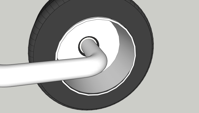
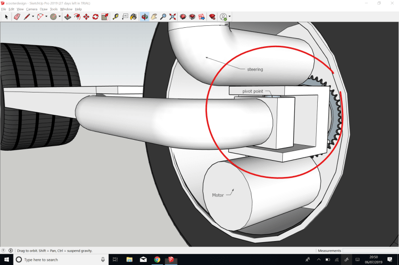
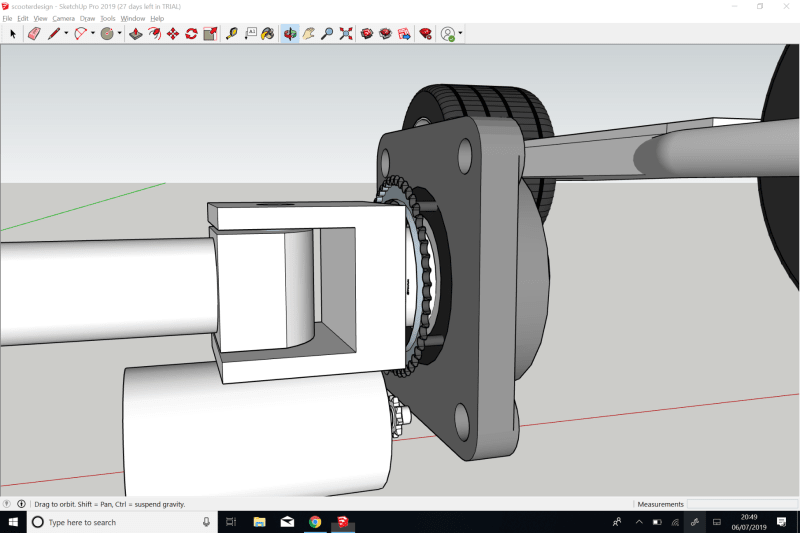
Im working a 2 wheel scooter type project and im looking at having a small brushless motor within each wheel. The back wheel is perfectly fine, frame/axle through bearing mounted to the wheel base with the motor mounted to the axle to drive the wheel. My questions is what would be your opinions on the best way to do the same at the front wheel but give it the ability to pivot so i can steer?
I only have an 203mm wheel base diameter and 100mm depth from the wheel base to the outside of the wheel to fit the pivot point, 45mm axle and the motor which has a 60mm diameter and is 103mm in length. Id ideally like to keep it all within the wheel base but cant seem to work it out.
Hoping you guys may have a solution i haven't thought of. Quick google sketchup mockup attached (to scale)
Thanks in advance


