Continue to Site

Eng-Tips is the largest engineering community on the Internet

Intelligent Work Forums for Engineering Professionals

  • Congratulations KootK on being selected by the Eng-Tips community for having the most helpful posts in the forums last week. Way to Go!

Air Causing Problems in Suction Pump Pipeline 1

Status
Not open for further replies.

Fooooks

Mechanical
Sep 15, 2016
48
Hi all, thanks for taking the time to read this.

I would like to know how a horizontal pipeline that is flowing a fluid reacts when air is added to it.

Background: I am looking to analyze the suction piping of a pump to program a variable frequency drive (VFD). Under normal conditions, the pipe is pumping vegetable oil from railcars to a tank with the use of a long suction pipe (10") and hoses (4") connecting to each rail car. We can determine the minimum suction pressure to prevent cavitation and can program the VFD accordingly. When the rail cars empty one at a time, then atmospheric air starts entering the system, at which time the pump and pipelines vibrate. I'd like to understand the fluid dynamics more on the suction piping so I can either a.) eliminate/evacuate the air from the pipe, or b.) set up the VFD to respond to the air in the system and slow the pump down.

So my question is this: If air is being pushed through the pipe, what is happening in regards to pressure, flow, cross sectional area, friction losses, specific gravity, and so forth? Attached is a rough sketch of the scenario.

I am open to give more information and hope this will serve as some informative and valuable discussion, as I cannot seem to find too much literature on the topic.

Thanks,
Fooooks
 
 http://files.engineering.com/getfile.aspx?folder=6bc1e4e1-45ff-4799-8d8e-22e6743ff9b0&file=Air_in_Pipe.jpg
Replies continue below

Recommended for you

Isolate the pump when the tank empties. Allowing air into the pump has nothing to do with fluid dynamics, it has all to do with entrained air and pump loss of prime.

It is a capital mistake to theorise before one has data. Insensibly one begins to twist facts to suit theories, instead of theories to suit facts. (Sherlock Holmes - A Scandal in Bohemia.)
 
Fooooks,

First off, when making a follow up post, please add a reference to your earlier one so everyone can understand what's happening, like this
I assume you still have PD pumps and not centrifugal as shown in your sketch?

"If air is being pushed through the pipe, what is happening in regards to pressure, flow, cross sectional area, friction losses, specific gravity, and so forth?"

Your pipe is below atmospheric pressure and hence is drawing in air. This is quite unusual for most systems so there isn't a lot of analysis and basically whatever flow you end up with in your main header pipe, unless it is very low, will still result in air being drawn in and hence giving rise to all sorts of vibration, pulsing etc,

But to answer your questions.
Pressure will fluctuate due to flow changes. What you now have in two phase flow which has been studied a LOT and hence I'm surprised you can't find anything suitable to read. Two phase flow however is a transient thing and very difficult to model accurately without using software and even then you don't get a very accurate analysis. Just take a bubble of air as it enters your system is at 1 bara and a certain volume V1. As it progresses along the pipe, the pressure reduces further. This doesn't affect the liquid to any extent, but at say 0.5bara, your bubble is now twice the volume 2V1.

All things being equal, the liquid flow will go down as the X sectional area becomes part liquid, part gas. SG goes down, but friction can go up as the gas can travel faster.

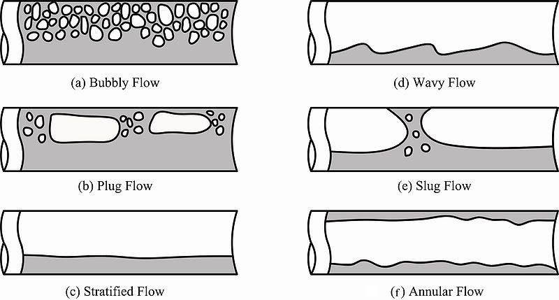
A lot depends on what the volume ratio is for your air / liquid as to whether your pipe is essentially fizzy liquid like you show or becomes more surge / slug like.
This gives you some idea of the possible variations.

800px-Chapter11j__3_b2ul0t.jpg


One thing you could look at or try is to use different size orifice plates on the hose connections to your header with the smallest hole on the nearest tanker. The aim would be to get all the rail cars discharging at the same rate and hence finishing at the same time. You do some analysis but trial and error may be just as easy...

Another option is to install a buried tank with a vent line higher than the top of the tankers and empty the header pipe into that and then pump from that tank, controlling on level for your VFD as the inflow reduces as tankers empty. It might take a bit longer as there is not the pump lowering the end pressure, but is much more of a turn it on and forget about it until the pump stops on low level in the tank / provides a notification that the tank level is low and hence unloading is complete.

Remember - More details = better answers
Also: If you get a response it's polite to respond to it.
 
In addition to the above comments, one of the problems with a larger pipe diameter is that it is difficult to push the air out unless the velocity is kept high. If the velocity is low, the air will not clear.
 
Artisi,
It is not often we get loss of prime during this operation. There are times when it happens, however, and we pinch or close down on the discharge valve and open up a bleeder line to purge the air until we can get a good prime again. By this time, the operators have noticed that there is an empty railcar and will close off the valve, eliminating the source of air into the line.

LittleInch,
Thanks for the feedback on proper etiquette on this site. The previous thread was asking to solve the problem of cavitation, and in this thread I wanted to learn more about two-phase analysis in piping under atmospheric pressure. I will be sure to link all associated references in the future.

It was to my understanding two-phase flow was the same liquid in two phases, and I did not anticipate information that would relate to a thick, viscous fluid with air in the pipeline. This is a fault of mine. I would imagine the flow looks to be "plug" or "slug" flow that you show in your attachment, due to the type vibrations we see during the pumping. Large vibrations occur every 4-5 seconds when a rail car is empty, causing our expansion joints to extend and contract pretty drastically.

The problem is that the rail car quantities are not always consistent and we do not unload from all of them simultaneously depending on the situation, we have plenty of railcars with plenty of different products. We have no budget for underground tanks also (but I love this idea most, maybe when we design a new track in our facility).

Bimr,
My initial thought is that the air is not getting stuck, but that we ARE able to push it through, which is causing the vibration in the pipelines. The end goal is reducing vibration in the system due to this air that is pushing its way through the pumping system.


Thank for all of the feedback, I'll continue to look into two phase flow.
 
I'm much more familiar with "pushing solid water" (er, pumping water with no bubbles) rather pumping light weight oils, but consider that even your vicious oils do flow slowly. Much slower than water. They're going to trap and suspend big bubbles of fluid between the air bubbles. That's part of the slugs and jerks you're you're seeing in the expansion joints.

The pump impeller (not a positive displacement ?) is getting some oil, some air, then all oil, then all air. So, from the (excellent) sketches above, you're going to see plug flow and slug flow.

At a full tank car, warm weather, warm fluid, what is your limiting capacity? The gravity pulling the oil down through the long flex hoses to the pump suction, or the capacity of the pump to push it out? (Certainly not a question that comes up with water pumps.)
At a full tank car, cold weather, cold fluid, what is the limiting factor? Does your pump EVER cavitate or generate slug flow then?

Most limiting condition is probably, cold weather, cold fluid, near-empty tank. (I say cold weather and cold fluid separately: Your pipes and pump might be "warm" down in FL or Houston, but the tank car was sitting in North Dakota for three weeks. The fluid is going to take a while to heat up to local "room temperature" .)

As a quick fix, get three accelerometers/vibration detectors. Put one on pump suction pipe, one on pump casing, one on pump discharge pipe. Maybe a backup on the pump discharge pipe (four total.)

At full tank to 1/2 tank, run the pump as fast as possible. (Probably your current PLC setting, the "regular" operation.)
From 1/2 to 1/4 tank, run at 3/4 or 5/8 speed.
From 1/4 to empty, run at 1/2 speed, but with a cutout to 1/8 speed if any one of the three accelerometers exceeds ???? point showing the pump is surging and vibrating.

And tell your operators to WATCH THE PIPES, they can do the above manually and let you know what actually works based on varying railcar load levels and different oils and temperatures. I would not expect this to be an unmanned operation done by mindless robots.
 
racookpe1978,
My apologies, it is a positive displacement pump (we have sliding vanes and rotary gear pumps in this application).

I'll dig deeper to find some typical flow rates that we have and get some more information. Like you pointed out, the scenarios vary widely with the temperatures and we have no viscometers. The customer does not provide this information to us in the SDS(s) either.

With the worst case conditions that you mentioned, yes the pump cavitates, our operators get a feel for the liquid when they start the pump and do not run it full speed based on the first few minutes of good flow.

I have started a budget to add some vibration sensors, working on it now. I am on board with this suggestion! Do we need to get a contractor more experienced with vibration and acoustic to do a startup or procedure for this type of work?

There are multiple pumps on the tracks (we have 7 tracks) and multiple movements, so there are times when operators are AWAY FROM THE PUMP for up to 30 minutes, during which time 2 of the 6 rail cars they were unloading simultaneously could have emptied. So adding some PLC logic to slow the pump during cavitation or vibration is the end goal, to prevent damage while the operators may be away from the pump.

 
The other thing maybe to do is track for a few days the levels in each car for different numbers of cars etc (ideal for an intern or someone similar) and then you can see how much quicker the nearest car to the pump takes to offload compared to the cars further down the siding.

Or maybe just double or triple the hose length for the first two cars, double it for the next two and have a single hose length for the rest?

If your aim is to minimize vibration then the best way is to avoid air in the system in the first place.

However the vibration idea is a great one to deal with all the possible permutations which sounds like you have a lot of ( length of cars, substances, temperature etc.) Trying to spot pressure fluctuations is harder for a simple control system so vibration is a good options.

2 phase flow in viscous oils is more likely to be a slug flow given the large difference in density and viscosity.

Remember - More details = better answers
Also: If you get a response it's polite to respond to it.
 
Fooooks,

Unloading product from rail cars is not new. There are multi-phase pumps available in the market.

Get input from from pump manufacturers. They have pumps with control units specially built for cases like yours. One example is Gould Pumps.

Ganga D. Deka, P. Eng
Canada
 
I don't think they want to spend any money. ....

Remember - More details = better answers
Also: If you get a response it's polite to respond to it.
 
With the devices you have at hand now, would suggest using the current sensor for each of these motors at your motor control centre - a rate of change of current draw can be used to slow down the VFD or speed it up in steps as required (current draw would bump down steeply when air passes through the pump). For example, let this DCS controller compute this rate of change (every 5seconds say); if the rate of change exceeds a given value, this controller could be configured to reset speed down a notch. If it doesnt detect a rate change that exceeds this value for say 15seconds, it allows the VFD to ramp up a notch. You can build up on this VFD ramp up/ down logic to suit your preference. If the existing current sensor at MCC for each of these motors isnt sensitive enough, ask your electrical engineer to change this sensor out for a better one. See if you can trend this current draw ( current vs time ) to select a suitable rate of change value.
 
GD2,
We have contacted our Goulds rep for their PumpSmart services. I was under the impression it was only for their pumps, which are centrifugal pumps. We use positive displacement due to low NPSH requirements and efficiency with more viscous products (and we use the same PDs all over, and changing pumps would be a major overhaul project on the track). I will need to check if they can retrofit onto our existing positive displacement pumps.

While it is not new, I believe our set up is outdated and I have not been able to put my eyes on any other terminal's rail car unloading applications to get a feel for what else is out there. For example, I heard another terminal near us sloped their pipes down towards their pumps, so that air would rise to the highest point, which I believe vents to another tank. This is what an operator told me over the phone (take it with a grain of salt).

Compositepro,
We cannot have the pumps shut off automatically because we may be pulling from multiple cars simultaneously. If we have it shut off at the first sign of air, then we still have product in other rail cars that need to be emptied as quickly as possible.

LittleInch,
We do not have a budget set aside for this project, but operations has complained to engineering and maintenance so much that we are trying to be as proactive as possible to come up with a solution and present costs to management. We would not, however, be able to get something approved that is a major change to our rail system. The cost of some down time due to a pump failure (we have spares) or a branch connection failing is less than adding multiple underground tanks to an all concrete track, for example, just to fix the vibration.

Georgeverghese,
Thank you! That sounds like something we could easily do. That answers the question I was trying to ask (sorry it was scrambled): what changes in the system can we trend due to air entering the piping and modify the VFD or other parameters? We do not have the capability to trend the current draw data into our SCADA system. So we would need to add that first and start trending it before programming the VFD's logic based on what you are proposing.

I hope I responded to everyone. It sounds like utilizing vibration sensors along with trending current draw and modifying the VFD or just adding a PLC to control the VFD may be the best solution at this point.

 
Not sure if you missed my simple idea to add some friction losses to the nearest cars to try and even out the emptying time by adding another hose length or two to the cars which empty first?

Georges idea of monitoring current is good and probably the easiest to implement so long as your switchboard is up to it.

I can believe the sloping pipe which I would guess removes air at the start, but unless their product is much less viscous, you would need to isolate the vent otherwise it could pull in air.

You could have things like individual small sump pots on the hoses such that they provide a signal when the flow from the tanker stops which could close that particular valve, but that's getting rather sophisticated...

Remember - More details = better answers
Also: If you get a response it's polite to respond to it.
 
If your hoses don't CONTINUOUSLY slope (at least 4% for vicious (sic) oil, would be 2% for water) you MUST provide that function immediately: It will improve flow (shorten tank car drain time, reduce fluid losses and contamination losses due to oil being "left in the hose" between cars, and smooth (not eliiminate) transitions as one car in a train empities before the rest.

Cheapest and fastest (and it looks like "cheap" sells the idea) idea for the train yard is a inclined "ramp" for the longest feeder pipe to the furthest probable tank car. Then each closer tank car drops down into the top of the inclined pipe. Has to be at the top for venting and air relief when slugs and mixed plugs of oil and water go by. Ideally, the ramped pipe would be below the bottom of the railcard, you really don't want a low spot where the hoses down to the gravel (ground) and back up to their feeder connection.
 
LittleInch,
I would need to run some hydraulics to determine if the orifice plates would work and what our new flow rates would be. But the cars also line up in different spots every time, or the same spots could be used for a different hose or header pipe, so I think it could over complicate it, but I'd need to check the rail schedules and P&IDs for opportunities to install these.

I looked into options that would close the hose valve when the flow stops, but the solution I looked at might close the valves early if there was a large amount of vortexing at the bottom of the rail tank. I am not familiar with your suggestion for sump pots, but I will continue to look into this option. The downside is that there are near 80 rail car spots, each with 1-3 individual hose and valves, this would be quite a bit of an overhaul to add valves.

Racookpe1978,
Unfortunately, they do not continuously slope, the hoses connect at the bottom of the rail car, go down to the ground, and back up to the connection (which connects to the top of the header pipe). This is due to hose length, but there are times they spot the cars off of their mark, so that we need some extra slack in the line. The header pipe is not much lower than the bottom of the rail car connection either.

When you say "air relief when slugs and mixed plugs of oil and water go by", do you mean the slugs would travel into the hose as it passes a feeder connection attached to a full (not empty) rail car? Like I said, our hoses and feeder pipe are not set up as you suggest, so I wonder how much of the air pockets would travel into the full rail car tanks when it passes by the feeder connection.

I can't tell everyone how appreciative I am of the conversation, every suggestion so far has been great, and I'm understanding the system more based on your replies. Thank you.
 
That's a degree more complex than it looks at first glance alright. Most offloading is a fairly routine repeat operation but yours sounds much more complex and variable.

Glad you understand a little more and let un know if any of the ideas work out.

Remember - More details = better answers
Also: If you get a response it's polite to respond to it.
 
It sounds like you have continuous varying flow conditions. Aside from expensive controls an atmospheric surge if installation permits would solve your problem. The rail cars drain into the surge tank and when the car is empty no air enters the pump suction because the pump is drawing from the surge tank. The surge tank oil level should determine pump start and stop. Once the optimum liquid velocity is determined there would be no need to change it. You need to determine if installing the surge tank is feasible near the rail cars.
 
Status
Not open for further replies.

Part and Inventory Search

Sponsor