Continue to Site

Eng-Tips is the largest engineering community on the Internet

Intelligent Work Forums for Engineering Professionals

  • Congratulations waross on being selected by the Eng-Tips community for having the most helpful posts in the forums last week. Way to Go!

Air Distributor Pipe Pressure Measurement

Status
Not open for further replies.

Doodler3D

Mechanical
Jan 20, 2020
188
All,

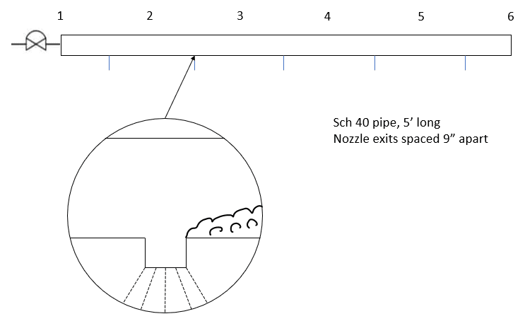
I've been tasked to improve a previous experiment for a soot blowing application. Air is being fed from a 30 L tank at 8 bar. The diaphragm valve pulses for 50 ms and the goal is to measure specific impulse pressure across the tube. Since this not a steady flow application, what are the best ways to measure and quantify the drop in pressure across the pipe. The previous experiment was performed 5 years ago and the only conclusion was that the application 'worked'. I'm trying to put some numbers to the claim. A few articles online mention pressure taps at locations 2,3,4,5. The previous experiment was performed with two transducers at 1 and 6. Obviously, it did not work because of the reflections at location 6 in pressure waves the end of the pipe. The turbulence at the air exits too significantly impacts measurements. I'd appreciate a nudge in the right direction.

Thank you.
Screenshot_430_mmqhmk.png
 
Replies continue below

Recommended for you

I think the sampling rate of the sensor would play a big part in trying to measure the effect of a 50ms pressure pulse. Getting several data points within the 50ms window won't be as nice as getting 100 data points in that same span. A lot of off-the-shelf industrial sensors will maybe have 1-2 data points in that span of time. Have a data capture setup to measure that will also be important.

If you want the best picture you'd probably want a transducer mounted at the inlet and every nozzle.

Several fast response, high accuracy lab transducers and a data capture system isn't cheap or easy (relatively speaking, compared to process sensors and controllers), which is probably why they stopped at "it worked" last time.

What is the "improvement" you're after? Better spray patterns? More volume? More consistency between the first and last nozzle?

What is the size of the header, each nozzle, and what is the inlet pressure being pulsed at?
 
I do not have details of the sensor/DAQ used, but the DAQ sampled at 600Hz. 5 years ago they were still using a primitive, hand-held 4 channel DAQ from the early 2000's. The improvements are as you mentioned - spray patterns, pressure impulse and equalization of flow. The tank is at 8 bar and the tube exhausts through the holes with a diameter of 3/8". Φ = 1.315" and T[sub]wall[/sub] = 0.133"

2ms response would mean 25 data points?
Link
 
Check the math on velocity of the 8-bar pressure opened up to your header, see what kind of ballpark timeframe you're expecting to see the pressure reach the end of the pipe. That should give you a reasonable estimate for how quickly the sensors need to sample if the resolution of that event is of importance, as well as an idea of how long you're seeing "stable" flow and how much data is needed during that time.

Creating a more even pressure in the header could be accomplished by increasing its diameter relative to the spray ports, but you'll need to balance velocity and pressure if it becomes more of an expansion chamber relative to the short window of time.

If your "nozzles" are simply open ports you could investigate some actual nozzles to give you a spray pattern that's more even. The pressure drop of the manufactured nozzles might also contribute to better pressure profile of the header if you're no longer losing disproportionate amounts of flow from the first opening(s).
 
It's the sensor that's key. 1 to 2 milli second response time looks pretty fast to me and you might need t think about sonic velocity / pulses in the tubing or pressure connection.

No point gathering 600 points per second if the TX only updates every 100 m sec....

Remember - More details = better answers
Also: If you get a response it's polite to respond to it.
 
Thank you all, I will post an update when the DOE is complete. There's surprisingly thin amount of information available on compressed air applications like soot blowing and blow molding.
 
You might get some useful data by recording the test with a high speed camera. Adding tracer smoke to the environment or to the compressed air might be necessary.
This video at about the 2 minute mark has a short segment showing discharge of a firefighting agent, which shows the utility of video in examining a test of the sort described.
 
@FacEngr, those are pricey. I did some PIV at university, the optics and lasers were ridiculously expensive. I have limited budget to set up a 16 channel DAQ.
 
Not knowing the size (or cv) of your valve I have to wonder how much air is actually being released in 50ms.
And of course, the temp drop will be considerable so the volume of air will be even less.
Given that the pressure wave will travel at sonic velocity it is straight forward to predict the time response needed.
Your transducers and logging system will need to be fast.
A camera isn't a bad idea, there are a few Sony options under $1,000 that will do 250fps at 1920x1080.
An RX10 II will do 1,000fps at lower resolution. Not exactly super expensive.

= = = = = = = = = = = = = = = = = = = =
P.E. Metallurgy, consulting work welcomed
 
Status
Not open for further replies.

Part and Inventory Search

Sponsor