Continue to Site

Eng-Tips is the largest engineering community on the Internet

Intelligent Work Forums for Engineering Professionals

  • Congratulations GregLocock on being selected by the Eng-Tips community for having the most helpful posts in the forums last week. Way to Go!

Air Flow shear in Pipes

Status
Not open for further replies.

Barry P

Mechanical
May 31, 2022
11
I am working on a project that feed air flow and pressure to Air Pumps to supply fresh water and air to fish in a Fish Farm.
I need to operate three Blowers (two operating at one time and alernate with the third)
My issue is when two blowers are operating at the same time one of the blowers will dead head, either due to the shear or air pressure in the pipe.

The System:
Operating pressure is 55 inWC and 800 CFM each Blower.
The air travels through a common pipe.
The Blowers are operating with a VFD and a common pressure Transducer.
I use 8" electric actuated valves on the discharge of each Blower.
Sequence of operation.
- Blower #1 and #2 operate Producing 800 CFM @ 55 inWC eac. The Valve for Blower #3 is closed.
- After a set time (1 week) Blower #1 will stop and Blower #3 will start. All three Blowers Close during the Transition and Valve #1 Closes while Valve #3 opens.
This is done to stop any of the air from travelling in reverse through the Blowers.

How can I get two Blowers to operate at the same time through a common pipe without one dominting the other?

Thank you
Barry P.
 
Replies continue below

Recommended for you

You can't without some form of added control.

You can accomplish the needed control by synching motor RPM across the two blowers that are operating and allowing RPM to change according to pressure feedback, you can throttle blower flow prior to entry into the common duct, etc - there are multiple ways to skin the cat. But if all the blowers are 'blind' to what the others are doing, you won't have a lot of control.
 
I'm not really following the operation at changeover.

You say no1 will stop and no 3 starts.

But then you say all 3 "close". What does that mean?

Does no 2 keep going but ramps up to compensate?.

The speed controller should give it the same rpm to each blower which is in operation.

If the units are fairly identical then you should get to a worst case of 60:40 split as units are rarely equal.

Remember - More details = better answers
Also: If you get a response it's polite to respond to it.
 
We had a similar issue with 2 AHUs.

Design put 2 AHUs supplying air head to head to a common duct.
Head to head means that one AHU was in one end of the duct and the other was on the other end.

Even if the AHUs were exactly the same, there was always one that was pushing the other.
We tried to balance, fine tune BMS controls, adjustments and when we thought that we had manage to find a sweet spot, a terminal VAV would open and close and one of the AHUs would overtake the other.

We ended up separating the 2 AHU systems.
 
Thank you for your comments.
SwinnyGG
We have tried syncing the VFD's with no luck.
We are operating at 90 amps. 4800 rpms.
And we are using one common transducer.

LittleInch
Thank you for your request for clarification.
Operation #1: Blower #1 and Blower #2 are operating while Blower #3 is not. Valve #1 and #2 are open and Valve #3 is closed.
Operation #2: Blower #2 and Blower #3 are operating while Blower #1 is not. Valve #2 and #3 are open and Valve #1 is closed.
Operation 3#: Blower #1 and Blower #3 are operating while Blower #2 is not. Valve #1 and #3 are open and Valve #2 is closed.

The issue is that we cannot get two Blowers to operate through the same pipe without one of them dominating the other. We require two of these blowers to be able to create enough flow hand head for the system.

MedicineEng
Thank you
We are redesigning the system to operate in two separate piping lanes.
We will be operating Three Blowers with Blower #2 operating as an alternating and back up Blower.
We will run 3 Blowers and 4 valves with the middle blower (#2) having two valves tied one to each lane.
The trick now is that the vales must actuate open and closed fully before the blowers are activated. If not the air pressure will turn the blowers backwards and cause the vfd's to over amp.

Thank you for your interest and comments.
 
But what is the system flow and pressure and what does it look like in terms of air pressure versus flow?

What do your fan curves look like?

How is the pressure control linked to each blower?
do they talk to each other?
What actually happens to each VFD when this happens (i.e can you plot speed over time for each one.
Ever tried putting it into manual?
And set each blower the same speed? and then slowly ramp up?

I don't understand how syncing the VFDs got you the same issue?

does the system only need one blower working at full speed?


Remember - More details = better answers
Also: If you get a response it's polite to respond to it.
 
Sorry NOT 90 Amps. 90 Hertz.

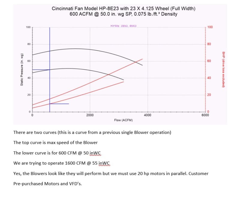
System flow is a total of 1600 CFM and pressure required is 55 inWC.
See attached Blower curve.
There is only one common Transducer the reads the pressure off the side of the pipe not the velocity pressure.

When both are operating the one Blower will operate at an elevated rpm to meet the required air pressure while the other will deadhead and the fan casing will get hot.

We control the VFD's through a PLC and we have operated them manually. The same issue happens.

I feel the issue is happening in the pipes with the air velocity.
I may need to create a larger header were the two chambers meet to help eliminate the velocity.
 
No curve attached.

Also do you have any other points on your system curve at say 800, 1200, 1600, 2000 at the least?

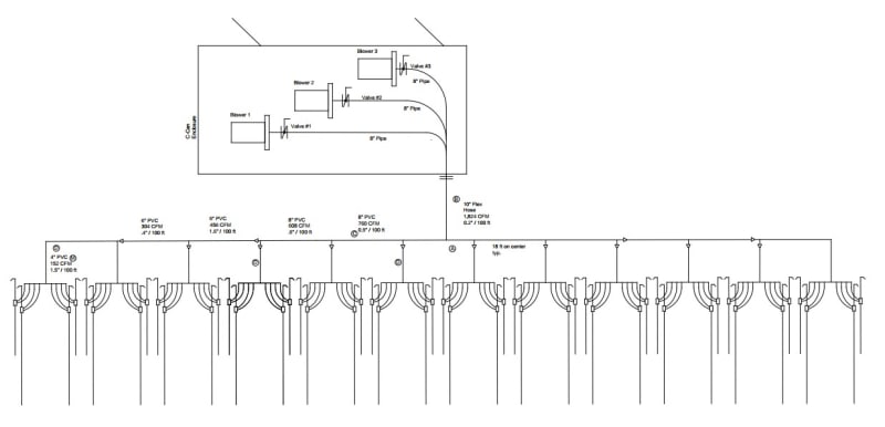
Also can you sketch the manifold where the blowers connect with sizes please.

Remember - More details = better answers
Also: If you get a response it's polite to respond to it.
 
Well that explains everything.

Basically your blowers are far too big for the duty and you're operating them on the wrong side of the curve. As soon as you have one blower going then the next one cannot generate enough pressure to start flowing until it is running at a higher speed than the first one. But then as soon as it does start flowing the first one will get dead headed and so it goes on.

That manifold arrangement is truly dreadful and you should connect each blower into the main 10" header with its own connection

Now even with your 20hp limit it looks to me like one blower can just about do your duty. What happens when you run one blower flat out up to your stupidly sized 20hp motor? Now you might not make your 1600 acfm @ 55in WC, but it looks like you'll be pretty close to me. Or buy a couple of bigger motors. Even 25 hp would do it I think.

Here it is for everyone:
Screenshot_2022-07-05_160839_okqgfj.jpg


Remember - More details = better answers
Also: If you get a response it's polite to respond to it.
 
Here's the "P&ID"

Screenshot_2022-07-05_161417_kofsv5.jpg


Remember - More details = better answers
Also: If you get a response it's polite to respond to it.
 
Thank you

I agree with everything you said.
I was given this project with this equipment to work.
Not knowing that much about air flow and pressure/velocity.
I normally deal with water.

This is my other solution to this that may work.
See attached.
Do you see any major issues other than the header.
I have to fit this in a 20 ft Sea-Can with an office.
 
 https://files.engineering.com/getfile.aspx?folder=4e743d49-e04e-469c-bbc6-f77d03145e85&file=PID_2.pdf
I think that could work.

Your blowers are still too big but you would share the load that way.

Will one unit not do it though?

Remember - More details = better answers
Also: If you get a response it's polite to respond to it.
 
Yes one blower will work but this is a critical application.
So if a Blower or drive fail the system will still operate until it is repaired.

Thank you for your input.
Very helpful and reassuring.
 
So why not run one and then if it stops just start one of the other two? They should start very fast.

But you need to do something as the current system just won't work. You can't beat physics....

Remember - More details = better answers
Also: If you get a response it's polite to respond to it.
 
Barry P said:
Yes one blower will work but this is a critical application.
So if a Blower or drive fail the system will still operate until it is repaired.

I feel like the others in this thread are saying the same thing, they just aren't saying it explicitly, so I will. Put simply:

Because your fans are so oversized for the application, running two fans all the time and balancing the demand between those fans is not possible. There is no controls solution that will yield the result you want.

Based on the size of your fans and where they operate on their curves, you have only two options to make this system work:

1) Replace the fans with units which are properly sized to provide for the air demand while running 2 fans in tandem

2) Revise the control scheme so that only 1 fan is running continuously, with double redundancy. You'll have to work out some wrinkles during changeover between fans, but if your process can handle a little bit of air flow fluctuation during changeover it's a survivable scenario.

As LittleInch just said.. you can't beat physics.
 
Thank you for all your feedback.

I now have some backing when I am told to make it work when it will not.


The key part is that you are operating in the part of the curve where as flow increases the blower develops MORE pressure. This is quite strange and is why most people won't initially believe you.

The only way you could get this maybe to work is to run two blowers at a fixed speed more than min and then modulate the valve and control on flow on each blower.

Even then I suspect they will just fight each other all the time as they are simply far too big

Remember - More details = better answers
Also: If you get a response it's polite to respond to it.
 
Thank you
One Blower will supply enough pressure and head. Barely.
If this is not enough then there will be more issues.
- Upsizing the motors to 25 will require the VFD's to be upsized and the disconnects as well as the backup generator.
- I cannot go to a smaller Blower because it will no produce enough flow.

My other thought would be to build a large header to reduce the Shear Pressure that is probably contributing to this issue.
Using individual transducers, one for each Blower.
If this works I can then operate three smaller Blowers with smaller HP. and run on the right hand side of the curve.
This would be for the next system.
 
Status
Not open for further replies.

Part and Inventory Search

Sponsor