Continue to Site

Eng-Tips is the largest engineering community on the Internet

Intelligent Work Forums for Engineering Professionals

  • Congratulations KootK on being selected by the Eng-Tips community for having the most helpful posts in the forums last week. Way to Go!

AISC Design Guide 9 Normal Stress Checks for Torsion 1

Status
Not open for further replies.

CARunderscore

Structural
Nov 12, 2015
28
I suppose this should technically be in the Codes forum, but things look pretty dead over there, so...

As alluded to in this thread:
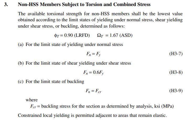
the Section H1 strength checks for doubly-symmetric shapes in flexure (and, therefore, flexure in combination with other stresses) of steel members in AISC 360-16 - Specification for Structural Steel Buildings are expressed as functions of the plastic section modulus instead of elastic section modulus, at least as long as buckling does not control. However, the methods of Section H3 for checking torsion are stress-based, and the maximum normal stress allowed by Equation H3-7 for combined normal stresses due to axial force, biaxial bending, AND torsion is lower than the stress allowed by Section H1 for axial force and bending only.

I can't imagine the intent is for a beam with negligible or zero torsion to "fail" a torsion stress check while passing the combined axial/flexure check, so I'm thinking that one of the following is the case:

1. The language in Section H1 regarding "members constrained to bend about a geometric axis" is meant to preclude situations where appreciable torsion is possible. But even then, Equation H2-1 for "other" members is a function of plastic section modulus for some sections.
2. The clause in Section H3 "Constrained local yielding is permitted adjacent to areas that remain elastic" is meant to permit localized yielding at the flange tips under strength-level loads. But AISC Design Guide 9 (referenced but not adopted as part of AISC 360) pretty explicitly uses elastic section modulus for strength-level checks.

Thoughts?
 
Replies continue below

Recommended for you

I'll take a stab at explaining it, but I can't comment on AISC specifically because its not an area I'm that familiar with.

The reason I believe you can take up to the plastic section strength for normal flexure is formation of a flexural hinge is pretty dependable (stable) mechanism for dissipating energy.

Fast forward to torsion, the same concept does not apply, if you get some plasticity in the flanges, it's potentially an unstable ductile mechanisms. Additionally it may affect overall equilibrium of the system if it relies on the torsion being resisted for equilibrium (think of it as being analogous to overloading a cantilever, you've formed a mechanism if a flexural hinge forms). Hence the checks involving torsion simply ensure the steel remains below the yield stress, and hence remains elastic.

I'd note a similar concept applies for torsion in steel in most standards where its covered, it's more or less meant to be taken as the member needs to remain elastic with limited inelastic action due to the combined bending, axial and torsion related stresses.
 
OP said:
Thoughts?

1) I take the section shown below as effectively saying that, when combined forces and torsion are considered, everything should remain elastic which is in agreement with design guide nine. Yeah, the last statement muddy's the water a bit but I don't take that as implying that one has full-on license to run with a plastic design if they wish. It's worth keeping in mind that this section applies to open cross section members of arbitrary shape. There's room for all manner of wacky stress distributions/concentrations once one veers into the exotic. As for why this situation should be constrained to elastic stresses where as other scenarios go plastic, my guess is this:

a) Computational expediency. Tracking and prosecuting a plastic design on a member where the normal stresses are coming in from biaxial flexure, axial, and warping stresses would be a nightmare. The case flexure and axial alone is much more tractable I think.

b) Available relevant testing. I don't know for certain but suspect that not a lot of testing has been done on open members subjected to axial, bi-axial flexure, and torsion simultaneously. As such, dialing stress levels back a bit and keeping thing simple strikes me as prudent. In contrast, I believe ordinary beam columns without torsion have benefited from a fair bit of testing.

2) Most importantly, I feel that the interaction equations need to not be viewed as things that are technically correct in any rigorous, mechanics of materials way. They're not...at all. They're more like the elliptical iteration equations/curves that we use for concrete anchors sometimes when there is an interaction between shear and tension. We accept that they're good enough but recognize that the pretty, simple curves didn't just fall out of the one big equation of the universe or anything.

Another interesting idiosyncrasy that pops up when one thinks real hard about using plastic flexural capacities is this: if you take your flexure to the point that you yield your flanges, how can your beam then possess any meaningful unbraced length for LTB? The flanges would offer no lateral resistance to buckling.

c01_whd88f.jpg
 
Thanks, guys.

KootK, I read Section H3.3 the same as you. I guess what I'm struggling with is that this situation implies that a guy leaning on a fully-utilized column constitutes an excessive torsional load, based on the code. There is no such thing as "negligible torsion" because even zero can be too much. Based on what you're saying, I need to regard this as an artifact of the code and make sure that I both meet code and satisfy reality. As usual. In my current real-world situation, I think I can justify alternate load paths that I was previously neglecting.

And, let's face it, the other reason this is annoying is that software will unhelpfully report "torsion" failures if torsion checks are enabled.

 
This is one of the least practical sections of the current AISC code. One of the things you run into when developing software is trying to avoid "discontinuity" between your code check equations. By that I mean a beam with no axial load should have essentially same code check as a beam with a very small positive or negative axial load. Right?

The only place that I'm aware of in AISC where this really falls apart is with drop down to elastic stress levels when torsion is present. There really needs to be better agreement between that section and other sections. To me, this is a true error in the code. For beams whose primary loading is torsion and which may be subject to slight bending, this may be reasonable. But, for 99% of the steel members that I've seen it feels ridiculous.

Now, Design Guide 9 goes into a lot more detail about what sort of stresses are produced in wide flanges subject to bending (i.e. torsional warping). I would argue that it makes more sense to convert these warping stresses into an "equivalent" weak axis bending moment. Add that into the actual weak axis moment and do your code check that way. If you do it that way, there is good agreement in the code check when you have zero torsion and when you have slight torsion.

I believe this is the way RISA handles code checks that include warping stresses. But, you might want to check their help file to see limitations of their method.
 
I should point out that most programs do not calculate torsional warping stresses (and you could argue that even RISA doesn't calculate them correctly).

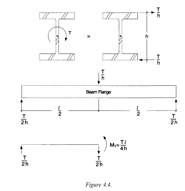
In that respect, I always recommend doing a quick "equivalent Tee" hand calc whenever torsion is a maybe design consideration for a Wide Flange or Channel. The equivalent Tee method is described in the AISC design Guide... See Figure 4.4.

image_jr3vxy.png


Essentially, you view the Tee alone as resisting that weak axis bending force.

The thing I really like about the equivalent Tee analogy is a)It's supposed to always be conservative b)It gives the engineer a physical understanding of where the warping normal stresses come from.
 
OP said:
I guess what I'm struggling with is that this situation implies that a guy leaning on a fully-utilized column constitutes an excessive torsional load, based on the code.

A strict read of the math might imply that but I guarantee you that's not the intent of the code writers. In the world of structural engineering, there's simply no space so tight that there's no room for the application of reasonable judgment. I suspect that most seasoned engineers would treat an insignificant amount of torsion as precisely what it is: an insignificant amount of torsion. If truly concerned, one might evaluate the torsion contribution to normal stresses and, if that's less than 5% of Fy, set Torsion = 0.

OP said:
And, let's face it, the other reason this is annoying is that software will unhelpfully report "torsion" failures if torsion checks are enabled.

Yeah, in the world of automated design, stuff like this always presents a problem. My thoughts on that:

1) I'd like it if code writers would acknowledge the ubiquitous nature of automated design and, going forward, set code provisions up to avoid mathematical discontinuities like this. A good example is how the phi factor on concrete slides with transition function as things move from compression controlled sections to tension controlled sections.

2) One might choose to view this situation as your software actually having done you a favor. As you implied, the answer here is probably to adjust your model such that the member(s) of concern don't attract the pesky amounts of torsion that seem to be giving you grief. So your software's effectively alerted you to your own modelling error.

 
This topic in general might be worth submitting to the AISC'S Modern Steel Construction magazine Q&A column to see if their experts would be willing to take a crack at weighing in.

JoshPlum said:
I should point out that most programs do not calculate torsional warping stresses (and you could argue that even RISA doesn't calculate them correctly).
In that respect, I always recommend doing a quick "equivalent Tee" hand calc whenever torsion is a maybe design consideration for a Wide Flange or Channel. The equivalent Tee method is described in the AISC design Guide... See Figure 4.4.
Essentially, you view the Tee alone as resisting that weak axis bending force.
The thing I really like about the equivalent Tee analogy is a)It's supposed to always be conservative b)It gives the engineer a physical understanding of where the warping normal stresses come from.

Yeah, that's actually what I was doing when I realized that more of my capacity was getting used up by the jump from plastic section to elastic section than from actual torsion.

About the "conservative" part: when I first learned about the equivalent flange/tee bending method, it was touted as "about 10-30% conservative". However, I found this 1977 paper by one Philip Lin that indicates the method is sometimes unconservative (never for pinned-pinned case, though) and sometimes "so excessively conservative as to be practically useless." The author subsequently provides tables with an adjustment factor to make the approximation more precise. The paper is available for download here, free for AISC members:


I didn't have time to delve too far into Lin's method, but I did a couple comparisons, and the results were pretty precise: within 1% of the results from the precise curves in Design Guide 9. I also suspect that the paper exaggerates the inaccuracy of the non-adjusted estimates for the majority of practical applications, though. Does anyone have any experience with Lin's tables or their merits relative to the basic method?

EDIT: I just noticed that DG9 does, in fact, qualify that the equivalent flexure method has limits. Actually, I had forgotten that it's even mentioned in the guide and had been referring to it as a separate thing, that paragraph is so tiny.
 
Interesting, I hadn't seen Lin's article / publication before. I was basing my comments on the "equivalent Tee" analogy on the Salmon and Johnson text book I have. It said, "It is apparent that the use of the flexure analogy without modification is a very conservative approach. In some situations it is so excessively conservative as to be practically useless".

He then gives a "modified" version of the method where you use tables to get a Beta value which adjusts the method to be essentially equal to the "exact" method of the design guide. To be honest, I have never used this modified method in a practical situation. I have always been satisfied with the perceived over-conservatism of the equivalent Tee.

But, maybe I'll have to take closer look at that publication to better understand what situations may lead to the method be unconservative. Thanks for pointing that out!
 
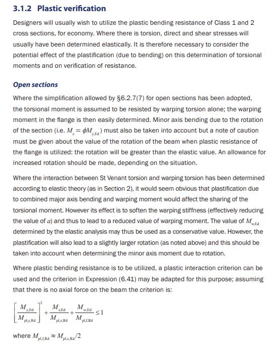
KootK -

Thank you! I already have a copy of that SCI guide, but I always forget to mention it!

I'm not as familiar with it as I am with AISC, but from what I've seen, it seems to be a good bit more practical than the AISC one. Meaning that it's a little more geared towards a practicing engineer as far as its recommendations are concerned. If I were starting over on this topic, I'd probably make this my "Go To" source for torsion of I shaped members and channels.


Status
Not open for further replies.

Part and Inventory Search

Sponsor