Eng-Tips is the largest engineering community on the Internet

Intelligent Work Forums for Engineering Professionals

AISC VS rigorous buckling analysis 2

FOX89

Structural
Sep 10, 2015
21
0
0
JO
Hello Gents,

When it comes to FEM rigorous buckling analysis using software (say SAP2000 or Etabs), what buckling factor limit would be reasonable. For now i assumed 1/0.9 = 1.11 (0.9 is Phi for compression).

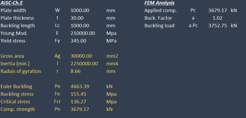
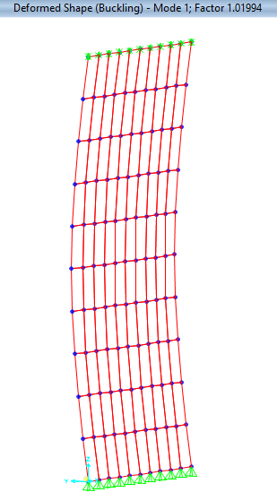
To verify this assumption, i have modeled a plate mesh on SAP2000 (PL 1000x30 mm) with pinned base and lateral restraints at the top. The compressive capacity was calculated based on AISC table 4-22 for kl/r to get Fcr and multiply by Ag, this capacity was applied as compression force on the FE model and carried out buckling analysis which resulted in buckling factor of 1.08 which is somehow near the 1.11. (note that i used non-linear case starting from P-delta and notional load to mimic geometrical imperfections).

As you know, buckling analysis utilize the modulus of elasticity and ignore material yield stress which is not the case when using AISC prescribed formulas. In other words, you will get the same buckling factor for different materials while different capacities will result from the empirical formulas. I have also tried using multi-layered non-linear shell with different materials but still got the same factor.

So my other question is; how can we perform realistic buckling analysis that utilizes material grade in order to verify and set reasonable buckling factor limits for the different types of elements.
 
Replies continue below

Recommended for you

Not sure I've understood your analysis. Can you redo it without the notional load and provide both sets of results. Also is 1000x30 the cross section or is 1000 the column height? (What is the kl/r value?). It would be good if you provided numbers for all parameters in your analysis. In any case you need to check a range of kl/r to validate your method. Very slender real columns have capacity close to Euler. Very stubby column much less than Euler.

Overall I don't see much benefit in what I think you're trying to do because it isn't a code method. Either use the column curve for design or do advanced nonlinear analysis.

Are you only interested in braced like you analysed or also sway?
 
I don't understand what you've typed. My best guess is you're trying to use SAP2000 to enhance or replace the calcs from the AISC Specification Section E3.

SAP2000's linear eigenvalue analysis should give you the elastic buckling stress. That's equivalent to Fe in Section E3, not Fcr like you're getting from Table 3-22 (or 3-14 in the the 16th ed. Manual).

The approach to using SAP2000 for my guess at what you're trying to do:

1. Use eigenvalue buckling analysis to get Fe.

2. If Fy/Fe <= 2.25, then compute Fcr (renamed Fn in 2022) using Eq. E3-2. Otherwise, compute Fn using Eq. E3-3.

3. Compute Pn = Fn * A.

4. Apply the phi factor for LRFD or Omega for ASD to get the available strength.

5. Compare the available strength to the required strength from LRFD or ASD load combinations.
 
FOX89 said:
When it comes to FEM rigorous buckling analysis using software (say SAP2000 or Etabs), what buckling factor limit would be reasonable.

I don't know what you are after here but to use a buckling factor from a linear buckling analysis won't work. As you say yourself, there is no strength involved in that analysis. What you can do is to use it to determine a "critical stress" for a plate or a "buckling length" for a member and then solve the rest with methods in the applicable codes.

To get a realistic capacity directly with FEM you have to use nonlinear analysis. And to only include the materials yield stress in the analysis won't suffice.
 
You are missing two huge components here - the first as other posters and you pointed out is the inelastic buckling failure mode. The second is the effect of residual stresses and initial imperfections. These are baked into the AISC equations as well. No idea what your problem is so I can't help, but the initial imperfections are the most important component when you have thin shell buckling.
 
Thanks all for your replies. I believe my thread was not clear.

I have many submittal reviews for shell structures including arched plates, curved metal shell (big logo), sphere like shells .. which are not predefined in AISC and shall be done in FEM. Most of the received design models are mainly addressing the principal stresses and von-mises stress checks along with buckling analysis. Now my argument is if you get buckling factor > 1.0, then the shell will not buckle, but is not necessarily passing the compression limit state as prescribed in AISC.

I did FEM for plate element as per the below shots and established that for high strength material (Gr.50 ksi, or 345 MPa), and did manually per chapter E. When i loaded the FEM plate with compression load equal to the compression capacity, the buckling factor was near to unity which establish that a buckling factor above unity will satisfy code equation. However if used code equation for mild steel this assumption will not be valid anymore.

AISC.CH.E_ogrv2n.png

FEM_duz4vx.png


So my question is how can we use FEM analysis to replace code equations, and what buckling factor shall we consider safe. Note that idea statica software use buckling factor of around 13 which will achieve equivalent l/r <= 25 and thus you can only check yield stress but this will be too conservative.
 

I have reduce the modulus of elasticity by 20% and used lateral notional loads equal to 0.003 to mimic imperfections (similar approach to DAM since i used k factor of 1.0).

I made iterative analysis considering P-delta and also used non-linear shell in SAP2000 but got matching results for two different materials !

yes exactly, but is it possible not to refer to code at all if i have cases that are not covered by AISC ? hope my previous reply is more clear now

 
Whoah! Your need to back right up on this. You are making some pretty scary statements here that suggest you designing complex structures without having much idea about what you are doing.

FOX89 said:
which resulted in buckling factor of 1.08 which is somehow near the 1.11
It is also somewhat near 0.99 which suggests that it will buckle spectacularly.

FOX89 said:
what buckling factor limit would be reasonable. For now i assumed 1/0.9 = 1.11 (0.9 is Phi for compression).
That is an scary assumption. For shell structure like you are talking about I'd be chasing 5.0 rather than 1.1.

FOX89 said:
Now my argument is if you get buckling factor > 1.0, then the shell will not buckle
And that is a terrible argument and shows you are not fully understanding what is being calculated and the addition complexities of buckling. AKA real world imperfections.

FOX89 said:
I have reduce the modulus of elasticity by 20% and used lateral notional loads equal to 0.003 to mimic imperfections (similar approach to DAM since i used k factor of 1.0).
Neither sound suitable unless you have placed the notional loads in exactly the right locations and directions.

I've done a fair bit of thin shell buckling FEA. Unless you are cross checking your results with tests or well establish empirical calculations then you have good basis of checking your work.
 
FOX89 said:
I have many submittal reviews for shell structures including arched plates, curved metal shell (big logo), sphere like shells .. which are not predefined in AISC and shall be done in FEM.

I am not in detail familiar with AISC. But in my experience FEM is often used to calculate a critical buckling stress. Then you can use models in the code to get allowable stresses.

FOX89 said:
I have reduce the modulus of elasticity by 20% and used lateral notional loads equal to 0.003 to mimic imperfections (similar approach to DAM since i used k factor of 1.0).

The key is to use the correct imperfections and I usually base them on buckling modes. That means that you deform the structure in the worst manner possibly. The next question is how large de imperfections should be. I am not familiar with AISC in this context but the current Eurocode (for steel) has some recommendations, next generation Eurocodes has much more. The purpose of the so called equivalent imperfections is that they shall include the imperfections and the internal stresses from manufacturing.

Once you have your model and have included the imperfections you can make a nonlinear analysis. That means that you do the analysis and include both that the material is nonlinear and that the geometry will deform nonlinear. If you first test to do the analysis without imperfections and then with them you will see a difference. The imperfections will initialize the failure. And then you need to determine what margin of safety you should use.

This was a short description on how this can be done. Using the buckling factor for safety assumptions, I would say that is not advisable.
 
human909, it is clear that i am trying to dig deep into this before carrying our any design or design review so i appreciate any suggestions or clarifications you have that would help move this conversation forward in a productive manner. You mentioned that you would chase 5 , please elaborate more on how you came up with this factor so we can discuss furthermore. From my side, i am trying to get some sense in comparing AISC equations to FEM analysis..

Thanks ThomasH, i recall that Eurocode 3 included some procedures for shell stability.. unfortunately i am not familiar with it but will give it a chance and comeback.
 
FOX89 said:
Thanks ThomasH, i recall that Eurocode 3 included some procedures for shell stability.. unfortunately i am not familiar with it but will give it a chance and comeback.

There is more in Eurocode then just shell stability. But regardless of it you use Eurocode or AISC, the purpose of the models (or equations) is to predict the strength (or stability) of a beam/column/structure. And the structure doesn't know what code you use [smile].

FEM. if it is set up properly, will will give you the same result as testing. And with proper use of the safety coefficients you should get the same result as the code gives you. The difference between code and FEM is that the code covers a limited number of "design cases", FEM can do "anything". But nonlinear FEM can be quite complex.
 
FOX89 said:
human909, it is clear that i am trying to dig deep into this before carrying our any design or design review so i appreciate any suggestions or clarifications you have that would help move this conversation forward in a productive manner. You mentioned that you would chase 5 , please elaborate more on how you came up with this factor so we can discuss furthermore. From my side, i am trying to get some sense in comparing AISC equations to FEM analysis..

Thanks ThomasH, i recall that Eurocode 3 included some procedures for shell stability.. unfortunately i am not familiar with it but will give it a chance and comeback.
That wasn't clear and your original post indicated enough lack of upstanding combined with significantly wrong assumptions that it was of concern.

Determining what value of buckling factor is appropriate really depends on the type of structure. My figure of 5 was used more as a indication of how far away you are rather than a specific value for your specific case which hasn't been elaborated on. Like I said you should either be looking at empirical approaches or test results to determine a suitable value.

Here is a quick run down relating to connections. The suggest threshold buckling value recommended with their software for connections is 15.
 
Still not clear to me exactly what you've done which makes commenting and helping hard. Some examples are 1.08 vs 1.02 buckling factor so you reanalysed without saying what you changed. Also you say you reduced E by 20% but your screenshot show 210,000 which is the full value. Did you reduce in both buckling and iterative p-delta analyses or only the p-delta? Because the 3752.75 buckling load is 80.5% of the 4663.39 Euler load. Pretty close to 80% but maybe just a coincidence. I still need to know the buckling analysis result without .003 notional load because it might not affect the result if you're doing what I think.

For different steel strengths, AISC give additional stiffness reduction based on actual stress vs yield stress. This will start to apply to 250 MPa steel at about the stress you've analysed.
 
. human909 you are correct, idea statica recommend this buckling factor since it is equivalent to kl/r of 25 or less, which permit checking the compressive strength using the full material yielding. However this would be conservative in many cases (atmospheric tanks or silos for instance).

Smoulder, i tried some rectification on the model. Yet i missed that reduction on E in both buckling and iterative p-delta thanks to your note. Now the buckling load from FEM is very near the Euler buckling load which does make sense if we have column element. However i believe that Euler curves do apply for columns only not for any type of irregular shell structures. As for the notional loads, the buckling factor was increased by around 8% without these loads. I might apply a global buckling mode as initial imperfect shape (using equivalent lateral loads) and check the respective effects.

Thanks all for your input but i still believe that i am far from reaching reasonable approach and acceptance criteria.
 
FOX89 said:
Now the buckling load from FEM is very near the Euler buckling load which does make sense if we have column element.

The terminology may differ a bit depending on the software. I work with all-purpose FEM-software and "Linear Elastic Buckling" is an eigenvalue problem. If you take "Euler buckling" it is the same thing. So, you can test the accuracy of the solver by modelling the basic Euler cases for members. The difference between the results is usually very small. If you have "Roarks Formulas for Stress and Strain" or Timoshenkos "Theory of Elastic Stability" you will find a lot more examples that you can use to check buckling factors and compare to FEM. But you cannot use these results as an allowed load capacity for design purposes.
As you mentioned yourself, the strength of the material is not included. And as others have mentioned, there are also other things not included [smile].

FOX89 said:
Thanks all for your input but i still believe that i am far from reaching reasonable approach and acceptance criteria

I think that statement is correct. But perhaps you are not so far from it. But if I go back to the title of the thread. AISC has a complete method for calculation the load capacity of a member, "rigorous buckling analysis" alone cannot do that.

You mentioned Eurocode, I think you mean the shell Eurocode EN 1993-1-6. In that you will find a number of different analysis "Levels". The highest level will give you a load capacity, but it may not be suitable for typical design work.
 
I will prob bow out after this because don't do enough shells to know codes fully. But some thoughts.

These are submittals. Make designer provide reference for acceptance criteria?

Don't think you can come up with acceptable buckling factor from scratch and it won'tbe just one number. Will need a code or other good source. Maybe Eurocode mentioned above. Because columns go through three stages.
1) slender. Real capacity related to Euler.
2) intermediate. Weaker relationship.
3) not slender. No relationship.
Then plates also have post buckling strength a lot of times. So capacity might be more than elastic buckling load if loss of stiffness is OK. This is different from columns where capacity always less than elastics buckling load. What you're analysing doesn't is really just a Euler column so not seeing this.

I guess your plate structures can be called braced so this bit prob not relevant. But Sway frames have higher required buckling factor than braced columns. I guess because sway frames move too much when getting close to buckling load. If you do have a deflection problem then you might want to have >3 buckling factor. Or >5 like Human909 said.
 
FOX89 said:
However this would be conservative in many cases (atmospheric tanks or silos for instance
).

I've done plenty of silos and while and while I would agree that buckling factor 15 is excessive, Im always cautious with silos. Silos regularly see loads at or even above regular design loads. They also have an abusive life. It is good to be conservative with silos especially if buckling is the likely failure mode.

(Likewise, I've don't vacuum vessels and they very much want to buckle and collapse spectacularly.)

There is much further advice I can give beyond repeat be careful and cross check with hand calculations.
 
Thanks all for your replies. I believe my thread was not clear.

I have many submittal reviews for shell structures including arched plates, curved metal shell (big logo), sphere like shells .. which are not predefined in AISC and shall be done in FEM. Most of the received design models are mainly addressing the principal stresses and von-mises stress checks along with buckling analysis. Now my argument is if you get buckling factor > 1.0, then the shell will not buckle, but is not necessarily passing the compression limit state as prescribed in AISC.

I didn't sift through all the replies (so someone may have already said this).....but this caught my eye. You are in the wrong code for shells. AISC is not meant to address them.

The safety factors for shell buckling can get very high (on the order of 10 to 20+) since initial imperfections can control. The safety factors used in AISC for LTB, Euler buckling, etc (on the order of 2 to 3) are not comparable. FEA can spit out all sorts of buckling values.....but I've never trusted FEA for that.

I faced a similar issue some years back....and some people recommended some resources:

 
Back
Top