Hello Gents,
When it comes to FEM rigorous buckling analysis using software (say SAP2000 or Etabs), what buckling factor limit would be reasonable. For now i assumed 1/0.9 = 1.11 (0.9 is Phi for compression).
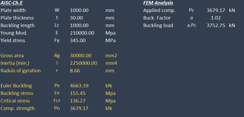
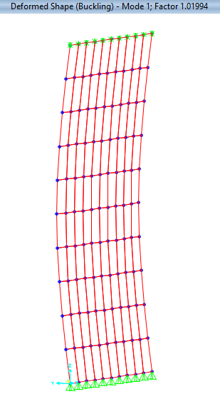
To verify this assumption, i have modeled a plate mesh on SAP2000 (PL 1000x30 mm) with pinned base and lateral restraints at the top. The compressive capacity was calculated based on AISC table 4-22 for kl/r to get Fcr and multiply by Ag, this capacity was applied as compression force on the FE model and carried out buckling analysis which resulted in buckling factor of 1.08 which is somehow near the 1.11. (note that i used non-linear case starting from P-delta and notional load to mimic geometrical imperfections).
As you know, buckling analysis utilize the modulus of elasticity and ignore material yield stress which is not the case when using AISC prescribed formulas. In other words, you will get the same buckling factor for different materials while different capacities will result from the empirical formulas. I have also tried using multi-layered non-linear shell with different materials but still got the same factor.
So my other question is; how can we perform realistic buckling analysis that utilizes material grade in order to verify and set reasonable buckling factor limits for the different types of elements.


![[smile] [smile] [smile]](/data/assets/smilies/smile.gif) .
.