Continue to Site

Eng-Tips is the largest engineering community on the Internet

Intelligent Work Forums for Engineering Professionals

  • Congratulations waross on being selected by the Eng-Tips community for having the most helpful posts in the forums last week. Way to Go!

Alignment pegs GD&T

Status
Not open for further replies.
Replies continue below

Recommended for you

Datum feature symbols are to be attached to the geometry that are used as the datum features - not to center lines; this is because on the actual part there isn't a center line to use. You can construct where it might be from the part geometry, so that's where the datum feature symbol goes.
 
SO both the drawings are wrong? Or is it just the right side one?
 
Both, I think. What on the part is used as datum feature C and for datum feature F? And datum feature E might be the tangent point, and that's where a datum target should be placed.
 
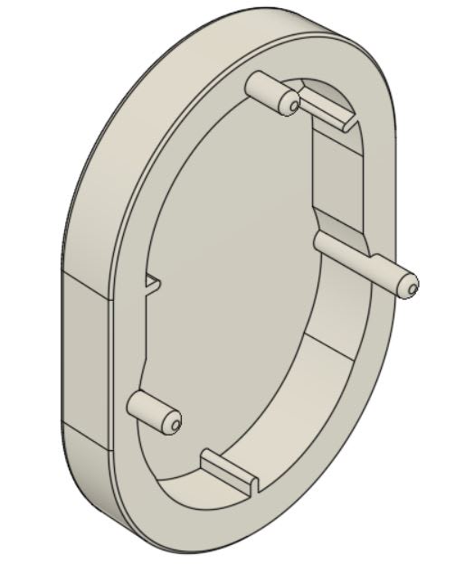
gdandT_f3kqqj.jpg

This is how the part looks for reference.
 
Yes - that would work to do what I think you want.
 
Why is the datum E wrong. Its at a distance of 14 from the top and passes through the center of the two alignment pins.
 
It could be either pin or both pins so that's unclear. Also, the [14.00] doesn't seem intended to locate the part relative to the pins, but the pins relative to the end of the part. Also, it's a problem to locate pins from themselves. Where they go they are right where they should be, but not in relation to the rest of the part.
 
Sharudu,

All your Datum Feature symbols should be attached to physical features specified as Datum Features. They should never be applied to theoretical planes, lines, or points. Theoretical datums (planes/lines/points) are derived from the physical Datum Features (or more accurately, their inverse Datum Feature Simulators). Notice the slot Datum Feature symbols in your attachment are applied to the width NOT the center line/plane.
 
Okay, 3DDave and chez311. I think I understand now. I have attached an updated file and I still have two ways to define the alignment pins. Are both right? Am I right to think that in the left drawing the alignment pins would be derived from datum B and would be biased to that surface and on the right side drawing the alignment pins would be derived from the center of the part making the part more symmetric along the centerline?
 
 https://files.engineering.com/getfile.aspx?folder=695a8dd0-3cd8-47bf-98ce-0a1a795fa019&file=GDandT_Drawing_2.pdf
That is it - and correctly noting the difference between choosing one side () and choosing the width ([J]). Which to choose will depend on what gives the more desirable result. [B} is useful if having one side line up is important and [J} is useful to even out any differences.
 
Finally I understand it.. Thank you very much guys..
So on the female part, (which is similar to the above part but instead of pins it has holes where the pins can go) do I dimension it similar to what i did above? And also do I need to provide an mmc on the holes?
Also the part is injection molded..
 
MMC offers more tolerance for variation, but it also allows more variation by, usually, including clearance. If the pins are to be an interference fit then RFS is the more usual choice.

Is it a plastic or a metal part?
 
In addition to what was pointed out about datum feature symbol placement, consider carefully which features you assign as datum features. Datum features and their precedence order should be chosen according to how the part is intended to be mounted in an assembly and the corresponding constraints of degrees of freedom. You say that the pins are used for alignment, but it isn't reflected in your datum references specification in the drawing on the left. The drawing on the right attempts to use two of the pins as datum references (if that is what E is...), and it results in all 6 degrees of freedom locked by datum feature D primary and E secondary, then F is redundant.

Edit: the above was addressing the first file you posted.
 
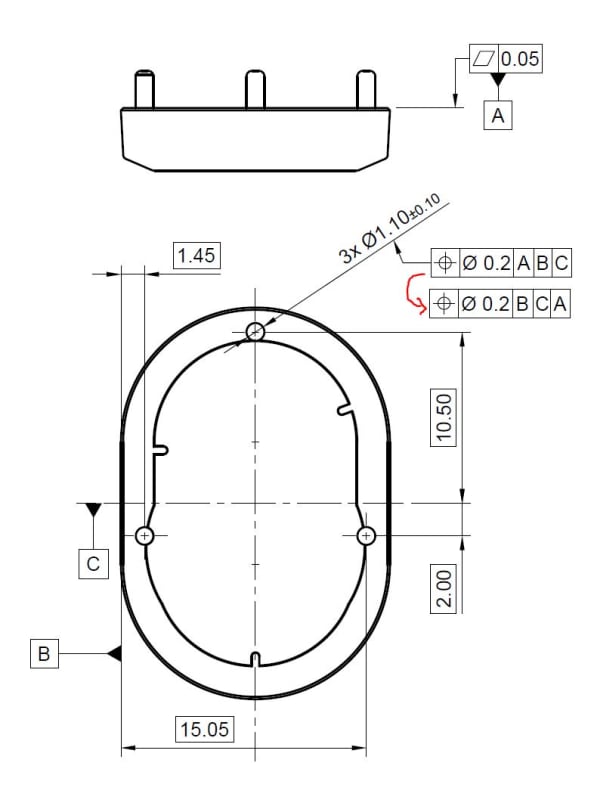
Thank you Burunduk. So i am assuming this is what you meant?
2_euuhhi.jpg


And on the right side drawing, I think the datum E is wrong from what I learned above.
 
Datum feature A should probably be the primary datum reference, I guess that it is expected to make the most contact with the mating part, providing initial stabilization at assembly. Is that correct? I am just assuming. Regarding B and C, it depends on how the part is mounted. I was thinking that you might want to use the alignment pins. If the pins are the locating features (all 3 of them?) consider doing it, but not the way you showed in the first file. I will try to prepare you a sketch later if you approve the idea that the pins are used to locate the part.
 
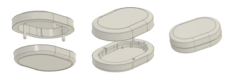
Yes, you are right about the datum A, it does provide stability and makes the most contact. I am open to pins being used to locate the part. Looking forward to your sketch. Thank you Burunduk. Here's how the assembly is if that helps.
3_vbkt7j.jpg
 
Status
Not open for further replies.

Part and Inventory Search

Sponsor