Continue to Site

Eng-Tips is the largest engineering community on the Internet

Intelligent Work Forums for Engineering Professionals

  • Congratulations KootK on being selected by the Eng-Tips community for having the most helpful posts in the forums last week. Way to Go!

Aluminum Compression Longitudial Deflection 7

Status
Not open for further replies.

jimmyjimmyv

Materials
Jan 27, 2021
24
I regularly perform compression tests on aluminum tubing. The tubing must meet a requirement of a minimum length deflection. Whoever drew the print up is using the length (before compression), multiplied by the yield offset value of .002 (0.2%). I'm wondering if anyone knows why an engineer would use this calculation to come up with a max value for the length deflection? My values are always higher as I use a calculator that utilizes "δ = (Pl)/(AE)" which takes into account; the load, modulus of elasticity, length and cross-section area.
 
Replies continue below

Recommended for you

Yes, it is the load divided by the cross sectional area of the part.

Say you have a 2" outside diameter round tube that has a wall thickness of 1/4". You would first find the cross sectional area: area of circle equal to π*r^2. So for this pipe, the area is π*1^2 - π*0.75^2 = 1.374 in^2

Now say you apply a load to this pipe that is equal to 48,000 pounds. To find the stress in the part you divide the load by the area. 48,000 lbs / 1.374 in^2 = 34,934.5 psi or 34.93 ksi.
 
what is the area of the part ? ... does 38kN yield the part ?

the deformation should be "less than" (not "equal to") 0.2% ... since teh real yield stress should be higher than the book value.

if the concern is doing two tests on one part ... use two parts (one for each test).
Else, from your research , would the manufacturing and tension test stresses impact the buckling behaviour ?
I'd've thought (knowing just about nothing of the subject) that tension stresses would increase the compression yield, but being non-uniform across the section they could upset the buckling test.

another day in paradise, or is paradise one day closer ?
 
rb1957 said:
what is the area of the part ?
The tube-end area is 0.1947 in2

rb1957 said:
does 38kN yield the part ?
yes, because the sample length is shorter after the compression.

rb1957 said:
if the concern is doing two tests on one part
No, we would never do that, we take multiple samples from the 100' extruded part

The rest of your questions appear to assume we are using the same part to test in both tension and compression, which we do not do.

BUT, we do stretch every part just after extrusion. This is the method we use to straighten extruded aluminum parts, as they are most often bowed.

According to the Bauschchinger effect, yield stresses induced in one direction (past the elastic limit) lower the yielding strength in the opposite direction.

 
"does 38kN yield the part ?
yes, because the sample length is shorter after the compression."

sorry, no ... length does not affect stress ... unless you're talking "engineering stress" and accounting for the area change due to volume ... but I don't think you are.
your stress is 37kN/0.1947in2 = 37kN/125.6mm2 = 300MPa = 42ksi ... which is approximately the ftu of 6061T6 !? I would've expected more permanent set in loading something to (almost) it's ultimate strength in compression !

"if the concern is doing two tests on one part
No, we would never do that, we take multiple samples from the 100' extruded part"
but this seemed to be your concern in your previous post (at least the way I read it) ...
"We have to [highlight #EF2929]tensile[/highlight] test 1 sample for every 1,000 lbs that we produce to verify alloy/temper; it is an ASTM standard B221. In addition, the part print states "Buckling Strength: permanent deformation after 38kN loaded shall be 0.07mm max. (38mm X .002) in the axial dir."

then you're concerned about the interaction of the manufacturing stresses with this test load ?

Can you run a test ? get a similar piece of extrusion, similar length, and load to a similar stress (stress = load/area) and see the resulting permanent set. I would be surprised if it were .2%. possibly this is a spec that can't be met ??


another day in paradise, or is paradise one day closer ?
 
I would like to clarify the following back and forth just to avoid further confusion:

"does 38kN yield the part ?
yes, because the sample length is shorter after the compression."

sorry, no ... length does not affect stress ... unless you're talking "engineering stress" and accounting for the area change due to volume ... but I don't think you are.
your stress is 37kN/0.1947in2 = 37kN/125.6mm2 = 300MPa = 42ksi ... which is approximately the ftu of 6061T6 !? I would've expected more permanent set in loading something to (almost) it's ultimate strength in compression !

I believe thatjimmyjimmyv is referring to the difference in length of the part before and after loading. He is saying that it must have yielded because it did not rebound to its original length after the load was removed.

 
yes, he is measuring the part after test (so PL/EA is not correct).

We now find out the part is loaded (in compression) to Ftu.

At that stress I'm not sure that .2% is the right amount of permanent set. Could be affected by how long the load is sustained/applied.

The impact of not stress relieving should be minimal, of course, depending on the amount of stretching. "stretch to straighten" should be minor.

another day in paradise, or is paradise one day closer ?
 
Yes, totally agree with you. I just didn't want jimmyjimmyv to get more confused with your reply. I did not take his comment as saying that length would affect stress. Instead he was saying he knows that it yielded (answering your question) because there was a permanent change in length.
 
dauwerda said:
I believe that jimmyjimmyv is referring to the difference in length of the part before and after loading. He is saying that it must have yielded because it did not rebound to its original length after the load was removed.

Yes, exactly

 
rb1957 said:
Can you run a test ? get a similar piece of extrusion, similar length, and load to a similar stress (stress = load/area) and see the resulting permanent set. I would be surprised if it were .2%. possibly this is a spec that can't be met ??

Unfortunately, I don't really have anything close to this at all.
 
rb1957 said:
We now find out the part is loaded (in compression) to Ftu.

You mean Fty, for yield strength, right? I would think going past Ftu would destroy the part.

and the ASTM values for Fty and Ftu are 35ksi and 38ksi respectively.
 
nope ... ultimate tensile strength, ftu (often also used as the ultimate strength in compression).

From MMPDS-06 (the replacement for Mil HandBook 5 which you can find online) ... for 6061T6, Ftu = 42ksi, fty = 36ksi

I used the data you provided ... load = 37kN (38kN), area = 0.1947in2 (thx for the units !), >>>> stress 40ksi

another day in paradise, or is paradise one day closer ?
 
rb1957 said:
nope ... ultimate tensile strength, ftu (often also used as the ultimate strength in compression).
ok, I see where you were going with it.

So, based on what you guys have said, it looks like I should be calculating the stress that will result with a given load in compression, when I'm trying to determine whether or not to accept a print, correct?

Using the Stress Calculator at Ominicalculator.com, I get a similar result as you did rb1957 (see below). In this particular case, if I based my decision on a calculation, I would be inclined to accept the print, as the stress induced during a compression test doesn't surpass the yield or tensile strengths of the material (we typically see 44.5 ksi Fty & 48 ksi Ftu, when "tensile testing" these parts. Strictly speaking from a calculation, the part shouldn't deform; unfortunately it does.

Calculation results:
[ul]
[li]Area = 0.1947 in2[/li]
[li]Force = 38 kN[/li]
[li]Stress = 43,876 psi[/li]
[li]Initial Length = 33 mm[/li]
[li]Final Length = 32.93 (initial length subtract max allowed displacement 0.07mm[/li]
[li]Change in Length = -0.07mm[/li]
[li]Strain = -0.0021[/li]
[li]Young's Modulus = -20,684,595[/li]
[/ul]

 
yes, but 43.8ksi is a very high stress for 6061T6, and it doesn't surprise me that the parts deform.

sorry again but things are getting confused (again). the .2% deformation is after the test, without the load. Under load, with a stress of 43.8ksi, the strain is higher. If the stress was still proportional, then the strain would be approximately .4%. because I think it's well above yield, I don't know what it is in compression (in tension it'd be close to 4%).

another day in paradise, or is paradise one day closer ?
 
Jimmyjimmyv:
In your investigation and history study, look at all the compression samples which failed, and what do they have in common w.r.t. straightening process & aging process anomalies, tensile strength (and yield strength), size/wall thk. variations, +/-, etc., vs. those which passed. Do these tell us anything to guard against? Do these suggest that under some situations we should just start with an assumption that we should discount the modulus of elasticity or yield strength by 5% to be sure that the compression test will pass? Test some un-stretched samples, do they show the same problems during the compression test?

You have been being helped by a several of the sharpest guys on this forum, for this type of problem, but you kinda keep talking past each other. You have to tell us much more about exactly what you are doing, what are these pieces for and how are they loaded in use, what the testing is supposed to show, etc., etc? Exactly what does the request for proposal (RFP) spec. say, let’s see a few with redactions as needed, and how does it vary from RFP to RFP? Then, your job or question is…, will your current tube size meet the spec. or, can you slightly change the wall thk. to meet this spec., what can we do to make it pass? I’m trying to understand if their spec. asks for what they really need, if you are interpreting it correctly, etc. We finally got the area of the tube out of you, but not all of the dimensions, nor do we know if it is round or square. You really haven’t laid your problem out very well for us, and you would be surprised how these little details influence how we look at a problem, or what issues come to mind with each change or added info. We aren’t asking for you to turn over your first born here, but we do have to understand many of these details and clear up some of the spec. requirements and terminology to better assess the situation. Contact me at rwhaiatcomcastdotnet. I’d be glad to talk with you a bit, where we can raise questions and confusions immediately, and come to some common point where we are all talking about the same problem, and in the same terms. You said you were having some problems with the engineering aspects and we may be able to straighten some of that out. I do believe that the Bauschinger effect is in play here, and the real trick to your problem might be how to work with it, or around it, to still meet your objectives. You are certainly not going to change it. I certainly don’t have all the answers, but the half day lags in your questions/comments and then further misunderstandings may just be further confusing the issue right now.
 
rb1957 said:
If the stress was still proportional, then the strain would be approximately .4%

I just went back through 10 random tests from over the last 4 years, with samples having varying areas and lengths, plugged that data into my old calculator that I now know calculates length deformation under load, and the calculator almost always projects a length change of 0.45% So, your .4% is waaaaay off, jk lol.


"Strictly speaking from a calculation, the part shouldn't deform; unfortunately it does."

have we, after a butt-load of posts, come to the problem description ? Do you have pieces failing the test (through "excessive" deformation) ?

I think the problem is with the part print, asking you to apply 37kN to the part, causing a stress of 43ksi, which is above the yield of 6061T6
and then restricting your permanent set to only .2%.

another day in paradise, or is paradise one day closer ?
 
dhengr said:
but you kinda keep talking past each other
Yeah, that's going to be my fault because I've dealt with the mechanical properties of aluminum forever, but never really looked at them any deeper than if they were in tolerance or not. I apologize for the delays in responses, I just now finished up our 5-day IATF audit, via Zoom no less. Aside from that, I do wish I could spend the time in here and discuss this until I have it figured out, but I'm the quality mgr at a company that provides 4 million lbs of aluminum into the automotive market per month through 150 tier-1 customers so, I get pulled away a lot during the day. I didn't realize anyone was wanting the area, as I've learned from these guys earlier that the calculation I need doesn't involve the part area. My 2nd post described the alloy, temper, shape, and length of what I'm working with.

All of these parts are made in the same process, same extrusion press, same stretching equipment, and aged in the same oven. The only thing I've noticed different between passed and failed tests, is that the wall is thicker on samples that pass compression tests, and not by much, maybe 0.002". If we could just make the wall thicker, we would be golden, but the customer specs the OD and the ID, we don't let customers spec all three dimensions. So for the last year we've been trying to make a tube with the OD at the top of the tolerance and the ID at the bottom, giving us a thicker wall. BUT, this is aluminum extrusion, if I've learned one thing in the last 30 years it's that, if you try to run a dimension at the edge of a tolerance, you will run material out of tolerance at some point during the 1,000s of feet you're extruding. In most cases, a little bit out here and there doesn't hurt, but with the finished part length being an average of 2.5", the customer or the customer's customer finds all of our sins. With the customer's cut length, they are making millions of parts out of our tubes, and when they find even ONE bad part, 1,000s are now considered suspect and have to either be inspected or scrapped.

[ul]
[li]These parts are used in automotive noise, vibration & harshness (NVH) applications, like motor and shock mounts and various brackets.[/li]
[li]Our direct customer only has the responsibility of cutting the longer parts we've shipped down to their customer's cut-length (typically not over 3"). They chamfer the ends, tumble the parts and ship them on.[/li]
[li]The prints that are sent to us are from our customer's customer. Our customer has no engineers, they simply want to know if we can make the part so they can bid on the job with their customer.[/li]
[li]The finished product utilizes two different tubes, both of which we produce; one large OD (up to 4")thin wall tube, the other tube has a small OD with a thick wall (up to 1/2")[/li]
[li]The small OD tube is held inside the large OD tube by vulcanized rubber.[/li]
[li]We make around 35 different OD/wall combinations of each type of tube.[/li]
[li]We perform compression testing on the thick wall parts and expansion testing on the large OD parts.[/li]
[li]Port-hole extrusion dies produce the extrudates at around 1,000f, which are cooled to approx. 120f by water immediately after exiting the extrusion die. The extruded lengths vary, but are generally around 100'. Every extruded piece is stretched an amount that will leave the parts straight and not bowed. The stretching process is the least-controlled process we have, mainly due to the age of the equipment that make it a very manual process where the ends of extrudates are placed into the jaws of immobile equipment (tail-stretcher), with the opposite ends being secured in equipment(head-stretcher)that is moved in reverse to tighten and then stretch the extruded lengths. Dimensions are measured before and after stretching.[/li]
[li]The extrusions are then cut to the final cut-length of 12', placed on racks and artificially aged to T6 temper.[/li]
[li]For parts weighing less than 1 lb/ft, the testing frequency is 1/1,000 lbs. For parts that are heavier, the frequency is 1/1,000'. We collect random samples from the lot of material after aging. Test samples for each compression and tensile tests are sectioned from the same extruded piece.[/li]
[li]For tensile tests, we are simply verifying that yield strength, ultimate tensile strength, and elongation are within tolerance for the alloy/temper.[/li]
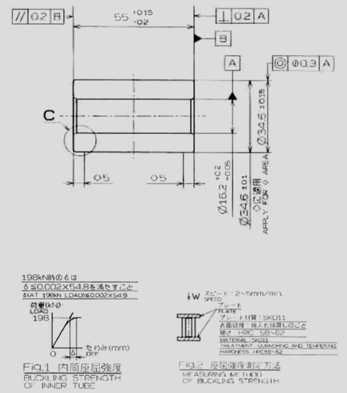
[li]For the compression tests, we are ensuring the parts meet the customer print requirement for max longitudinal displacement (almost all customer prints call this a buckling test?)[/li]
[/ul]
Print_-_Compression_Testing_qkba4s.jpg

I've attached data from a recent print quote. In this one, it actually looks like they are wanting a measurement with the sample under load, but the tolerance they give is entirely unrealistic.
 
rb1957 said:
I think the problem is with the part print, asking you to apply 37kN to the part, causing a stress of 43ksi, which is above the yield of 6061T6
and then restricting your permanent set to only .2%.

Yes, I think that is the problem. I think I've been blaming the .2% because that's the value that I have to meet, but as I've learned now, that .2% is what it is and cannot be changed. What needs changing is the load value.

This is why I think I'm going to use a calculator that gives me the projected stress which I can simply compare to our historical test results and determine whether to accept or reject the print.
 
It does not matter what .2% is other than the cusotmer requirement. It does not have to be related to the stress-strain curve, or an offset or anything - it is simply a customer specification expressed as a fraction of the part length. Odd perhaps but then most likely performance based requirements from the regulations that govern their industry.

Aluminum specifications are minimums and it is not unexpected to get more than the minimum sometimes. This may explain your pass/fail ratio.

The customer expects the part to yield or they would not be asking you to measure permenant deformation.

If a part is exposed to a load that exceeds it's yield strength, I'm not sure how you predict, control or limit the deformation.

If you want your parts to have zero failure, design them so the load does not exceed the minimum yield strength. You have done this by experimenting with thicker wall.

If you can't increase the wall thickness, you will need to more closely control the actual yield strength. Since you are the extruder, you may be able to do this with minor changes in the alloying elements while staying within the AA ranges for the alloy.

Would changing to AA6005A be possible, would it help (I find that extruders like 6005A over 6061 for uniform properties and ease of extruding)?

Would going to a T6 temper be acceptable, if not would going to T4511 or T4510 yield more consistent test results?
 
IFRs, you are right; although, they are referencing the yield offset value of .2%. you can see the reference in the graphic from their print. We've only had issues with 2 out of 35 part numbers over the last 13 years, so we wouldn't want to introduce another alloy (sku) just to address a couple problem children. Also, we are very limited in the aspects we can change, as we make to print, we don't design parts. Basically we have to live inside of a tolerance zone for all dimensions and chemistries. I think we're close to clearing this obstacle with in-house specs on the wall, and raising the OD and lowering the ID. My main problem right now is, this customer submits multiple RFQ'S every month, as more parts are being switched from steel to aluminium. Almost every print is just like the one above with the .2% of sample length deformation limit. I've learned my lesson with this part (not the one above), but I don't have a calculation with which to base my decision on whether or not to accept the part. Thank goodness rb1957 set me straight with my previous calculator or I may never have accepted another part, ever. lol
 
Status
Not open for further replies.

Part and Inventory Search

Sponsor