Eng-Tips is the largest engineering community on the Internet

Intelligent Work Forums for Engineering Professionals

An unusual feature (to me) on a steel truss bridge 1

Status
Not open for further replies.

spsalso

Electrical
Jun 27, 2021
942
0
0
US
Below is a link to a photo of a railroad bridge (build date 1961) over Highway 101 in Ventura CA:


I see that as being a two-span truss bridge.

I am wondering about the reason for the horizontal member along the top, immediately over the center pier. I believe usually this is empty space, in such a structure.

As in this delightful old bridge:


Can someone explain?


spsalso
 
Replies continue below

Recommended for you

I am not specifically a bridge engineer, but my suggestion would be that it is to achieve moment-continuity over the central pier.[ ] This increases both the strength and the stiffness.

I would therefore reverse the question.[ ] Why does your second bridge NOT have the additional members?
 
Because it doesn't need them?

Each span works perfectly well by itself.

There are thousands of multi-span bridges in the world designed like my latter sample, and they have generally worked for over a century. Why does THIS one have the extra piece?

Or, put another way: why bother to have the center pier? Belt and suspenders?


spsalso
 
I'll mention that the Ventura bridge is skewed, FWIW.

I do confess that I suspect the "extra members" are decorative. As in: someone said "The bridge looks so ugly with that big gap right in the middle. Isn't there something you can do?"


It could happen.


spsalso
 
It does make the span stiffer across that joint. Otherwise when the train goes over there is a mid-span sag of some amount on each side of the center pier and a high point at the pier. Tying them together prevents a sharp change in deflection at that spot. It may be on other bridges they make the trusses extra deep so the deflection is less noticeable and tying them like this saved some money in material.

The other thing to notice is that when the trusses are extra deep they can use weaker steel while still benefiting from the higher bending resistance, but as steel quality/strength improved they didn't need the deep section to have enough strength but needed to account for the loss of stiffness by tying the two spans together like that.
 
"It does make the span stiffer across that joint."

Stiffer? Yes, adding connections where there normally are none will add stiffness. But to the improvement of the design?

And then one can ask whether the "span" IS made stiffer. "...when the train goes over there is a mid-span sag of some amount on each side of the center pier..." We would need to examine the case of the train being on only half of the bridge, compared to on the whole bridge.
For the former case, I don't see a benefit--the one span sags, which distorts the other one--gaining what?. For the latter case, a sag in both "halves" of the bridge would put compression on the "special member". Would that be better met by a more common design?


For steel truss bridges, I don't see where seismic loading enters into it. As long as the bridge shoes line up with the abutments, the bridge stands. Except for that, I don't see how seismic forces would affect a steel truss bridge.

I question a steel truss bridge ever failing due to seismic, aside from abutment support.


spsalso

 
Spsalso said:
For the former case, I don't see a benefit--the one span sags, which distorts the other one--gaining what?.
That's why structural engineers earn the big bucks. 'Distorting' the other span causes it to apply forces (reactions) to the loaded span that oppose its movement - a stiffening effect.

We can't know the reasons that design decisions were made from photos. The continuous bridge looks shallower relative to its span but we don't know if the loading is also less. The simply-supported spans would handle movement of the supports better, but trains don't like that so you plan on it not happening.

The additional top member would typically be in tension BTW.
 
It's hard to say why one is simply supported and the other is continuous. Although railroads typically prefer simple spans because of fatigue and deflection concerns.


Truss bridges aren't immune to seismic forces. Trusses typically have a high center of mass and the inertial forces can create havoc.
 
I would think seismic problems for steel through trusses would be from rocking laterally, while the members under discussion would have their effect longitudinally.


I found a bit of a detail shot of the midpoint of the Ventura bridge:


Note that, at the lower part of the bridge center, it appears as if the two spans are separate--two pairs of bridge shoes, and a gap between the two adjacent gusset plates. The upper part is, however, continuous, with riveted gusset plates.


spsalso
 

It can rock laterally; it can rock longitudinally. Both conditions have to be accounted for in design.

Back to the original bridge. The top chord over the pier is a dummy member. There's pin clearly visible. Hard to see if there's one at the bottom of the vertical. It might have had something to do with erection stability during construction.

Inkedx_LI_ri1lge.jpg


Dummy members are found on cantilever trusses. They carry load during erection (depending on the erection method. Sometimes the center span is hoisted into place rather than assembled piece by piece.) but once the center span is installed they don't carry any load. This is taken from the Silver Memorial Bridge between Point Pleasant WV & Gallipolis Ohio.

Inkedy_LI_qcfmtp.jpg
 
It is a means to provide a ductile failure in the event of a loss of the center support, instead of a catastrophic failure.

 
No, Ron.

It is a means to NOT have an ugly visual dip in the middle of the bridge.

This is a bridge that EVERYBODY will see as they drive through Ventura. You leave that empty spot there, and everyone will think we're hicks from, oh, somewhere far away and backwards. THAT is unacceptable. Fill it in with some spackle, or something. Paint it shiny silver; they'll LOVE it!


spsalso
 
Interesting point Ron. Perhaps there was a concern about a high-speed derailment taking out a member. This is the first time I've seen this condition on a multi-truss span.
 
I wouldn't be so sure that it's not actually a continuous truss. Yes, it's on a double bearing pier, but the top member could still be a tension tie, I would think. If you guys have more information about that particular bridge and that top member, then I apologize.

I have seen 2 span continuous trusses, even here in Wyoming, so I know they exist.

Rod Smith, P.E., The artist formerly known as HotRod10
 
Sorry guys 'n' gals, it appears to be a decorative feature.

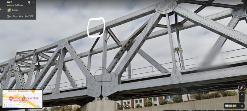
In this first picture, we see the "T" shape of the unusual addition (note that this is a skewed bridge).

the_T_djepsy.jpg


The top of the T has a pin in it. If you follow the darkish "I beam" over to the left, you will see another pin on the far side. TWO pins, one on each side! You will also likely note that, on the far side, the part of the T-top that goes to the right of the pin has a very curious termination. It sits on a little shelf. If you come back to the front plane, and also go to the right to the end of the T, and consider how far that end goes beyond the edge of the gusset plate, you will note that the end is attached to the rest of the bridge by FIVE rivets. NOT what one would expect in a major railroad bridge over a major freeway.

Now go over to the LEFT end of the nearer T. Note THERE that there are quite a few more rivet--upwards of 70. Now you could ask yourself: "If this top member is designed to accept either a compressive or a tension load, how come one end is so much more robustly joined that the other?" You could also ask yourself: "How come the lightly attached ends of these members are only attached to ONE gusset? Isn't that going to be a very nastily distorting input when/if a load arrives?"

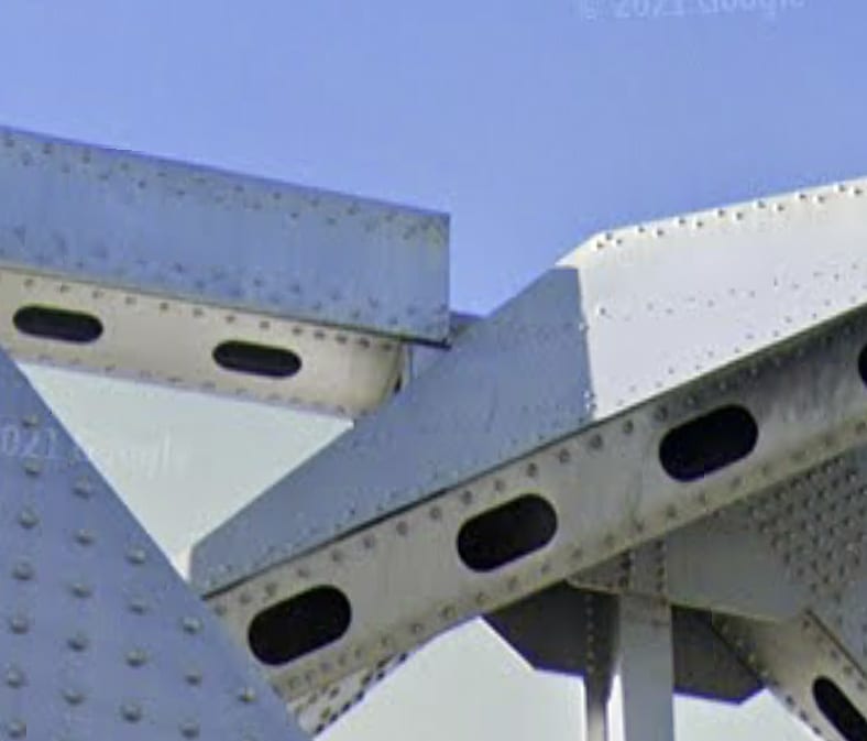
Below is another shot of the "strange termination":

detail--connection_of_T_end_povxft.jpg


You can see the cute little shelf the end sits on, and you can see that the member is only attached to ONE gusset plate.

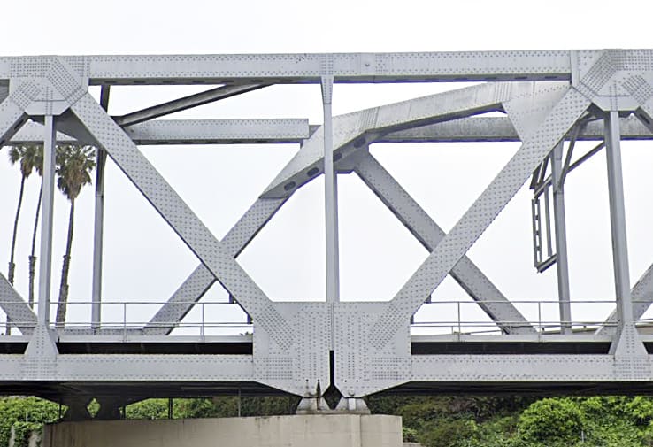
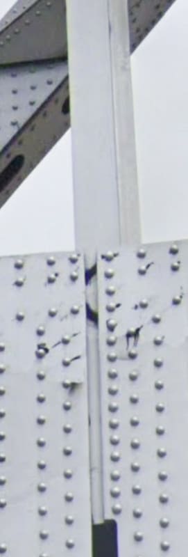
Now, examining the bottom connection of the vertical post of the T, we find that the left-hand vertical row of rivets do not actually join the post to the gusset. They miss the flange of the vertical post, and are only there for decoration.

detail--lower_end_of_post_fkdj8v.jpg


Should you suspect that the visual offset is due to the angle of view, note the same type of rivet row in the TOP of the post, shown below. THAT one clearly DOES go through the post flange.

detail--upper_end_of_post_eo36km.jpg


Also of note in the upper picture is the complete lack of reinforcement around the pin joint. Unusual for a load bearing point, isn't it?

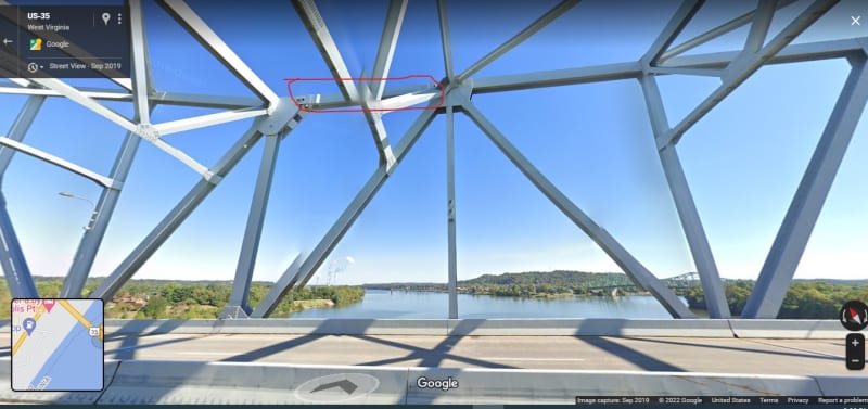
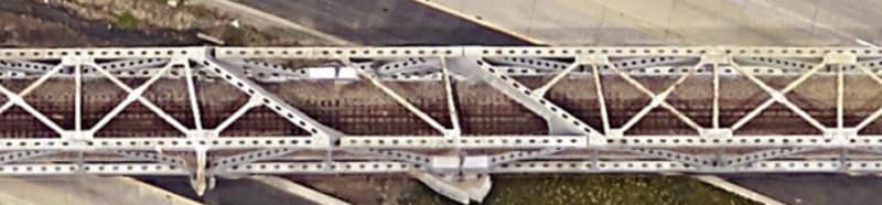
And finally, we have an overhead view. You can see the shadows cast by the unusual connection of the western (left) end of the T-top. You can also see an interesting semi-V shaped bit of bracing connecting the two T-tops. Note where they attach.

overhead_gudv88.jpg


It appears the two spans were installed separately, with the major part of the "T" structure attached to the eastern span. Once both were installed, the two remaining top pieces of the "T" were dropped in and attached by one pin and 5 rivets, each.


spsalso
 
Good sleuthing, Spsalso.[ ] The designers of that bridge have gone to a lot of trouble to achieve SOMETHING.[ ] But what?[ ] Pure cosmetics?[ ] Accommodate some strange behavioural quirk that results from the extreme skewness of the supports?[ ] (The amount of skewness only becomes obvious in your 07Feb22@22:33 post.)
 

don't bet the house on it just yet. We need to see the plans. We (bridge engineers) are not in the habit of adding unnecessary members. I gt the sense you live near there. If so, maybe you can get the plans from VCTC; the Bridge ID is 52.0178


In Street View the picture gets distorted depending on the viewing angle. Not even a half-assed engineer would connect a truss member with one gusset.


Truss pins are designed like beams. The outer pin plate looks fairly robust. You don't know what's inside the box.

If you look at the upper connection of the vertical - a lot of rivets for a decoration. From the photos at the bottom it's not possible to tell how it's connected to the gusset. It might be connected through the out line of rivets in each gusset; can't say with certainty particularly since the connection at the bottom isn't symmetrical.
 
Status
Not open for further replies.
Back
Top