Eng-Tips is the largest engineering community on the Internet

Intelligent Work Forums for Engineering Professionals

An unusual feature (to me) on a steel truss bridge 1

Status
Not open for further replies.

spsalso

Electrical
Jun 27, 2021
942
0
0
US
Below is a link to a photo of a railroad bridge (build date 1961) over Highway 101 in Ventura CA:


I see that as being a two-span truss bridge.

I am wondering about the reason for the horizontal member along the top, immediately over the center pier. I believe usually this is empty space, in such a structure.

As in this delightful old bridge:


Can someone explain?


spsalso
 
Replies continue below

Recommended for you

I live about 350 miles away--not what I call near. I have spent a bit of on-line time trying to get more construction info, but nothing yet. It would be swell to examine the plans, and/or to see the construction photos.

I wonder who would have plans. I can imagine the railroad (Union Pacific) since they own the trackage. Or perhaps state or federal government, since they paid for it. I don't think VCTC would be involved--I think they don't use the bridge.

I think there is only the single gusset at the joint in question because it carries no load. Adding another would only add needless expense. In the photo I posted (the second one), you can look right past the end of the member, and see the outside gusset. Therefore there is no INSIDE gusset. Hence: only one gusset.

Re: the quantity of rivets for the upper connection of the vertical. Note also the number of rivets on the OTHER end of the horizontal member--about 70, I said. Since this particular task was so unusual, it might have been a bit of a challenge to design the connections. The point of adding this bit of nonsense was to LOOK like a bridge. How many rivets does it take to LOOK like a bridge?

I fail to see how this "thing" could accept a real load: 5 rivets and a single gusset plate???????
Leaving out a connection between the bottom of the vertical and one of the two gusset plates it lands on? Non-symmetrical much?


spsalso
 
I've been thinking about the way the "add-on" pieces were attached to the rest of the bridge. It feels like the connections were designed intentionally NOT to transmit load.

Leaving out the 5 rivets for now, each piece is hinged at one end with a pin, which allows rotation. At the other, it rests on a plate, that allows sliding. There is a large gap at this latter end. And it's all done by intention. This is a flexible and movable connection.

Back to the 5 rivets. Those are a puzzle. On the one hand, none are needed for the above concept. On the other, if it's just for decoration (as the one vertical row of rivets appears to be at the bottom of the post), why not place a larger amount than only 5?

I'm pretty sure the reason for only 5 CONNECTING (as opposed to "fake") was that they would fail before having a significant effect on loading of the bridge members.


spsalso
 
I wonder who would have plans. I can imagine the railroad (Union Pacific) since they own the trackage. Or perhaps state or federal government, since they paid for it.

The railroad would have paid for it, but the the state would have the plans as well, since it crosses over a public roadway. not likely you could get the plans from either of them. The FHWA has tightened security for bridge structural plans since 9-11.

I fail to see how this "thing" could accept a real load: 5 rivets and a single gusset plate???????
Leaving out a connection between the bottom of the vertical and one of the two gusset plates it lands on? Non-symmetrical much?

Some of those photos look strange; possibly composites that didn't sync? Google Street View? If that's what you're using, I wouldn't trust what you're seeing to be anything close to the reality. Street View warps the photos in an attempt to approximate what it would look like from an angle other than what the photo was taken at. It's usually only marginally successful.

It's also impossible to know what's cosmetic and what's structural. The structural connections could completely hidden by a facade.

Rod Smith, P.E., The artist formerly known as HotRod10
 
It shouldn't need to be said, but just in case it slipped by anyone, pinned connections can still be structural; they just don't transfer moment. Of course, outside of a few specific types, truss members are not designed to carry moment, anyway. A truss member with 2 pins, or even more, can still function as a tension member, which is all the top chord section in question would be carrying.

Rod Smith, P.E., The artist formerly known as HotRod10
 
I doubt the railroad paid for the bridge, since the railroad predated the freeway. The railroad MAY have paid a small fraction, to the extent that various entities considered the new bridge an improvement over a previous one.

I am aware that Google Street View patches its photos together. And I'm aware that distortions can occur from the process. If there is something that looks strange/distorted in any of them, and it's relevant, I'd sure like to hear about it. The photos I posted aren't the only ones that show these details, and the details repeat between them. If necessary, I could post more pictures showing the same thing.

I disagree that it's "impossible" to know what's cosmetic. That statement would have to be true in all cases, which is a tough prove.

Yup, facades hide things. But sometimes you can look behind them.

I understand that pin-connections can transmit tension. There are some delightful trusses that use them as bottom members. Tell me about how that's done when only one end of the member is pinned and the other is free-floating on a support bench.


spsalso

 
I just spoke to one of my colleagues, who informed me that riveted joints mostly went away in the mid-fifties, so it's possible, actually likely, that all of those rivet heads are cosmetic, and the structural members are rolled structural shapes, not built-up sections, and connections are actually welded.

Rod Smith, P.E., The artist formerly known as HotRod10
 
Interesting.

So that bridge, built in 1961, is "likely" COVERED with thousands of cosmetic rivet heads.

I LIKE it!


spsalso
 
According to Bridgehunter.com it is a "Continuous 2-span Warren through truss bridge", but that's just one source. The structure number is 52 0178. It's at 34[sup]0[/sup] 16' 37.4" N by 119[sup]0[/sup] 17' 27" W. I wasn't able to find any info on the structure type, but perhaps others know where to look better than I.

Looking at the photos, particularly #25, it does look like that part of it, at least, is actually riveted.

Rod Smith, P.E., The artist formerly known as HotRod10
 
Lots of people here thought/think the bridge is continuous.

Doesn't make them correct.

I also thought it MIGHT BE, at first. But I kept looking and questioning and wondering.......

Nope. It ain't.


Now, about those rivets:

partial_south_side_of_bridge_paq5pv.jpg


The above photo shows a bit more of the bridge, and I'm pretty sure those are real rivets. And I'm pretty sure that they didn't just stop there, but did the whole damn thing with rivets.

Tell your buddy that you found a riveted truss bridge built in 1961--I think he owes you a couple of beers on that one!


spsalso
 
There are rived bridges in NYC constructed in the early/mid 60's. Bit of history: It was the ironworkers union that objected to bolts. A riveting gang was 4 men; and bolting gang only needs two.
 
Riveted bridges completed in 1961:

Helena_Bridge--Arkansas-Mississippi_hvecrr.jpg
J._C._Van_Horne_Bridge--Canada_pc3o6a.jpg
John_A._Blatnik_Bridge--Duluth_Minnesota_vz5a7w.jpg
New_Martinsville_Bridge--West_Virginia_ax9cqu.jpg
Seal_Island_Bridge--Nova_Scotia_t4bteb.jpg
Throgs_Neck_Bridge--New_York_sufcbn.jpg


I thought six would be enough!

Rod,

Your friend is quite ignorant of the history of the trade. And yet he has opinions on the matter.

I would avoid him, if I were you.


spsalso
 

Throgs-Neck Bridge, a friend of mine is running the deck replacement job over there.


Back to our bridge. I found something yesterday indicating it's owned by VCTC. Unfortunately I can't find the link because my work computer only saves the history for the current day.


At the bottom of the post, the lower chords and end posts are connected with two gusset plates. It wouldn't make sense not to connect the vertical to both gussets.
 
According to this article, UP owns the bridge:

Link

According to this article, UP owns the bridge and Caltrans owns the land under it:

Link


If these are two independent spans with "decoration" between them, it would serve no point to connect the two lower gussets via the flanges on the vertical.

And anyone still thinking this is a continuous bridge has a lot of splainin' to do about the connections for that top member. It cannot take a load.

spsalso

 
Your friend is quite ignorant of the history of the trade. And yet he has opinions on the matter.

I would avoid him, if I were you.

I didn't say friend; I said he is a colleague, as in someone I work with at the Wyoming DOT. He may not know what the 'state of practice' in other states was at the time, but having done more than his fair share of the load ratings for the bridges in the state, including most of the truss bridges, he knows what he is talking about with regard to Wyoming bridges. As bridgebuster noted, unions can have significant influence on progress, or the lack thereof, in the construction industry. Unions have never been very influential here, though.

Rod Smith, P.E., The artist formerly known as HotRod10
 
If these are two independent spans with "decoration" between them, it would serve no point to connect the two lower gussets via the flanges on the vertical.

And anyone still thinking this is a continuous bridge has a lot of splainin' to do about the connections for that top member. It cannot take a load.

In your first sentence you seem to be arguing that these are not independent spans, but in the second, you seem to be asserting that you think they can't possibly be continuous.

I'm not sure how you came to the conclusion that the top member "cannot take a load". It still looks to me like it could very well take some tension. Maybe not a huge amount, but some. Given the height of the truss, it doesn't take alot of tension capacity to provide significant moment capacity.

Rod Smith, P.E., The artist formerly known as HotRod10
 
QUOTE:
"In your first sentence you seem to be arguing that these are not independent spans,..."

I'm not arguing that they ARE. I'm saying IF they are, there is no point to connect the two adjoining lower gussets above the pier by using the bottom of the vertical part of the decorative T. I don't think anyone assembles a set of non-continuous spans on piers and then does any kind of structural connection between them.

QUOTE:
"...but in the second, you seem to be asserting that you think they can't possibly be continuous. "

I am asserting that IF the bridge is viewed as a continuous truss, then the members of the T must be designed to take significant loads, just like the other elements of the bridge. And I fail to see that this is the case.

And the whole point of what I said in the quote you used was that I do not believe that the T element under discussion has any structural reason for existing--not to connect those bottom two huge gusset plates "structurally", nor to connect the two top chord sections "structurally".


QUOTE:
"I'm not sure how you came to the conclusion that the top member "cannot take a load". It still looks to me like it could very well take some tension. Maybe not a huge amount, but some. Given the height of the truss, it doesn't take alot of tension capacity to provide significant moment capacity."

If we go with your "...some tension. Maybe not a huge amount...", then we must presume that each end of the T will have the same tension loading (small though it is). Now, if the end that I claim has only one gusset connection using 5 rivets, there is no reason for the other end to have more than that. And yet it does. So why put lotsa extra rivets where they're not needed--why not only 5?

spsalso


For those of you who are still a bit skeptical of the "artistic" interpretation of this bridge:


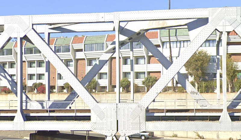
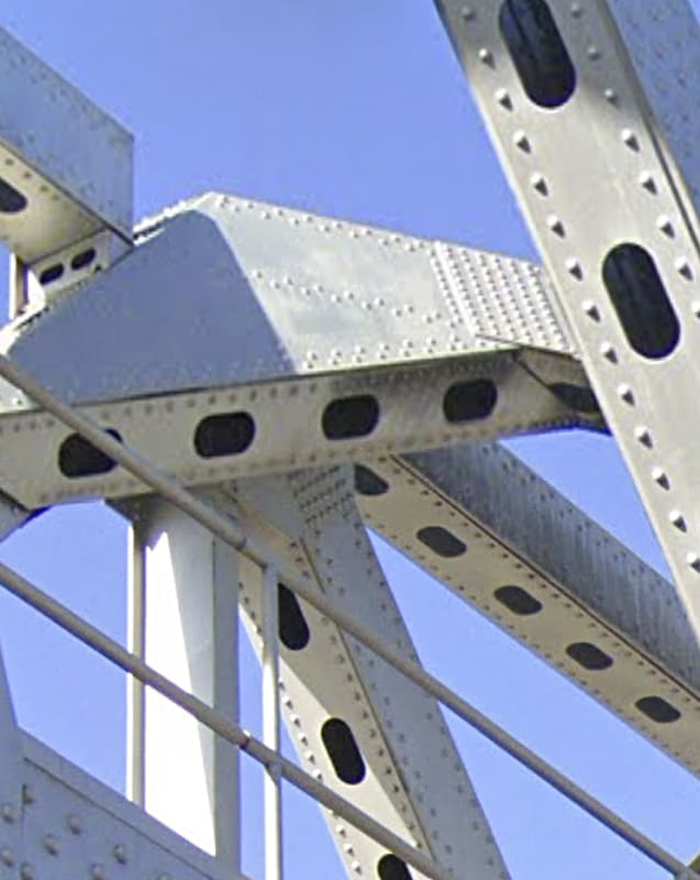
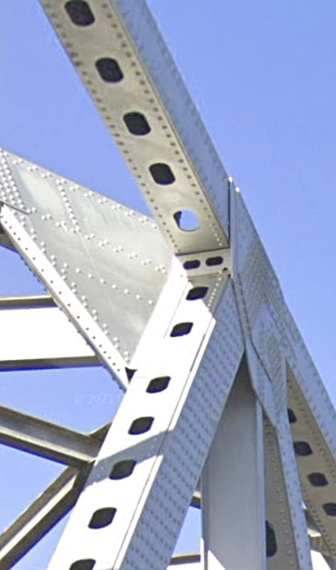
Below is a very good view of the western landing of the top member of the T, on the southern side of the bridge. You can see the landing pad, and you can see that the member stops way short of the next member. And you will note that there is no inside gusset for this piece. You can also see, peeking around on the left, the gusset that DOES cover the end of the member. I hesitate to use the word "attached" in this context.

landing_of_south_top_member_of_T_qzdnfl.jpg


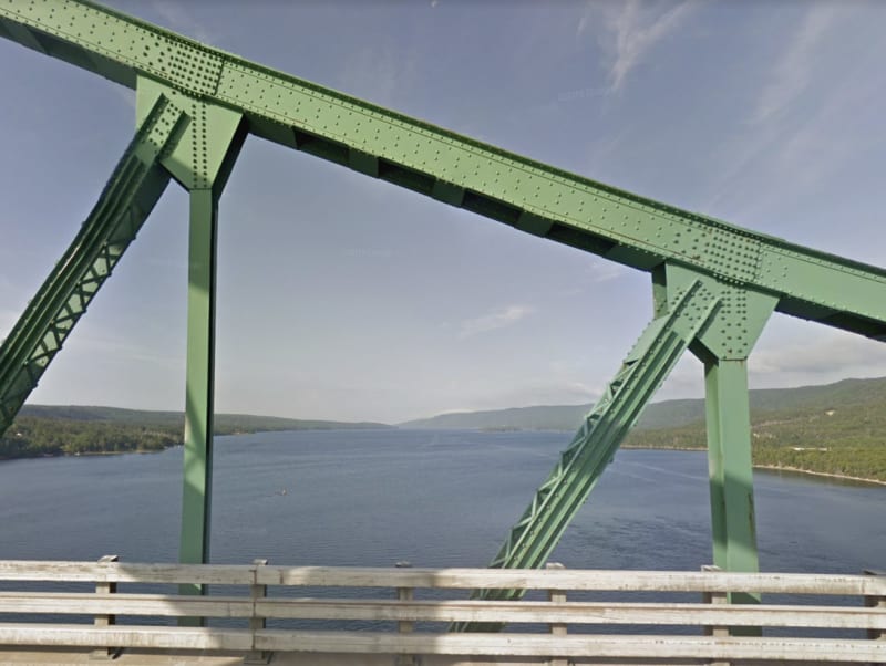
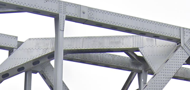
Next we have just about the only view of the landing of the north member of the T, at its western end. Of particular note is the lovely blue sky showing up behind the member--no gusset, no NOTHING.

landing_of_north_top_member_of_T_qoorft.jpg


This next one is quite good at illlustrating the extent of the engagement of the member ends into the gusset area. From this view, I am convinced that the 5 rivets I was crediting for attaching to the end of the member do not actually do so. That means that there are NO rivets attaching the ends to the only gusset available.
landing_of_both_members_of_T_vuey6n.jpg


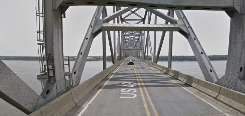
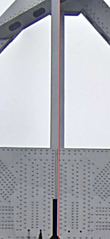
Here we move down to the bottom of the vertical member, where it ties into the two gussets. I drew a red line to indicate the right edge of the foreground vertical post. The grey that is to its right is the member on the FAR side of the bridge. This indicates that we are looking very close to squarely at the side of the bridge. And those gussets.

See where the line of rivets is for the right side of the vertical post. They either do NOT engage to flange at all, or are ridiculously close to the flange edge, and obviously improperly place.

rivets_on_bottom_of_vertical_post_hkmzdi.jpg


spsalso
 
Here's one for you: this is an old bridge with a relatively complicated design when compared to typical railroad truss bridges. We're trying to interpret the load paths from some cobbled together google images and images of bridge 'enthusiasts' that have been collected. Why does it matter?
 
Status
Not open for further replies.
Back
Top