Eng-Tips is the largest engineering community on the Internet

Intelligent Work Forums for Engineering Professionals

  • Congratulations waross on being selected by the Tek-Tips community for having the most helpful posts in the forums last week. Way to Go!

AN3 hole tolerance question 3

Status
Not open for further replies.

PJYDE

Aerospace
Feb 26, 2018
20
0
0
NL
hi all,

I'm working on the wing spars of a 2 seats light kit airplane.
The spars are already drilled and assembled by the factory.

Here an image of the root part:
2018-02-26_10-04-29_sodxkl.jpg


I found out that the thread-lock-paint on some AN3 bolts was broken, so I wanted to re-torque them.
But I was surprised that the bolt had quite some play in the hole.
The bolt has a dia of: 0.1870 inch
The holes vary from 0.1900 to 0.1950 inch
Is this too much?

I though about going to a NAS6603-16 bolt because they are a bit thicker: 0.1885 to 0.1895 inch.
But these are shear bolts and have a shorter thread, so it will be difficult to use a standard washer and AN365-1032 nut and still have 1 to 3 threads protruding.
Are these joins in shear or tension?

What would be the best solution?

Many thanks for your advice.
 
Replies continue below

Recommended for you

Do the measurements you are making match with the dimensions in the kit drawings? What do the drawings say about fit for bolts? Structural bolts are generally transition fit so there should be no "play". From the AN3 spec sheet the diametrical range is 0.186 to 0.189 so the holes are suspect to me. I would get in touch with the kit manufacturer and describe your problem.

Do not change the fastener type or size without talking to them first.

Keep em' Flying
//Fight Corrosion!
 
@LiftDivergence
I've asked the kit manufacturer and the reply was that the holes are "okay"...
On the drawings, I have, no hole dimensions are written, so that I don't know.

Based on the info I have, a 3/16 or #12 drill/reamer should be used for AN3: 0.1875 - 0.1890 inch
So the pre-drilled holes 0.1895 - 0.1950 seem to have too much "play".
That's why I'm concerned.

I'm thinking about the forces on these bolts, these bolts hold the outside spar doublers (around 15 inch long) at the root of the spar.
Are these only for thickening the spar at the root and are the forces primarily in tension, in that case I can imagine that the holes are okay.
But when these bolts face shear forces I'm a bit worried.

What could happen when the forces are in shear and the bolt has to much play?

Many thanks for your experienced advice.


When the forces are in shear, the friction between the clamped parts takes up the load. This is how most bolted interfaces work.

You're saying in this post:

Based on the info I have, a 3/16 or #12 drill/reamer should be used for AN3: 0.1875 - 0.1890 inch
So the pre-drilled holes 0.1895 - 0.1950 seem to have too much "play".

That you'd be ok with 20 thousandths of clearance; you're not ok with 25 thousandths?

For the purposes of handling shear load, clearance is unimportant. Sounds to me like this joint is designed not to have the bolts in bearing, and to use the clamp load to provide the required stiffness.

At the end of the day, by far the best course of action is to do exactly what the manufacturer tells you. By changing the bolt size, you open yourself up to the possibility of unintended consequences. Maybe those parts can't handle the extra clamping load a larger bolt can provide; maybe that joint's level of stiffness or compliance is important to the function and fatigue life of other parts. You have no way to know.

Don't change things unless the manufacturer tells you so.
 
PJYDE,

Maybe the drawing or a a picture showing more of the structure would help - you say we are looking at the wing root and I'm assuming the fasteners in question are shown with collars in the photo.

If that is the case it looks to me that this tapered leg doubler is installed over the web of the spar and picks up the vertical flanges of both the upper and lower chords. If I'm oriented correctly those fasteners would definitely be in shear.

But the bottom line is, if you have reported your question to the manufacturer and they confirm everything is correct, then clearly it is per design. So, you've done your due diligence.

Keep em' Flying
//Fight Corrosion!
 
Looks to me like a great deal of shear loading will be picked up by the flanges top and bottom, especially since they look like they get bolted together.
 
In your first photo, some of the bolts do not appear to show much protruding thread. Is there enough?
The paint you see is not "thread lock paint" it is a "witness mark". It performs no locking function. It is there to "bear witness" to two things: the presence of an inspector who verified the torque on the bolt before it left the factory, and it reveals when the bolt is loosened because turning it breaks the paint. So in your case, it did its job.

In general (not specifically to your aircraft) to make a shear-resistant bolted joint, you do not need the big AN365 nuts - those are known as "tension nuts". If you have a copy of AC 43.13-1b you can find the recommended application for these nuts. If you did want to replace the bolts, NAS6603 is a good choice but may be more expensive than necessary, and for this joint lower profile nuts suited to the NAS bolts will resist shear just fine and you may be able to put just as much torque on them. But that's not in the cards for this wing - you really shouldn't by changing the bolted joints from the one that passed the design and tests without approval from the holders of the design.

Actually, I would never use #10 bolts in any spar root unless they were installed with controlled torque such as Hi-Loks or the like. AN3's are 1950's fasteners and the world has moved on. But I'm nit-picking.

If all of the holes in question were drilled by the factory, then it's likely that the drill/ream procedure is detailed in a process specification, not on the drawing itself. The drawing may refer to the process somewhere, but since you mention it's a "2-seak kit" airplane, that's not very likely. The fastener installation data is not likely to be made available to you if it's on a proprietary spec.

I do not see a reason for these holes to be of concern, even if it can be shown that the AN3 bolt/hole size combination leaves a clearance fit in a shear joint. Firstly, as many have pointed out, the torque of each bolt ensures the shear load transfer. Second, the deflections in a wing structure in day-to-day flying don't need to take up all the clearance but the bolt torque prevents the slip. Thirdly, if discussing ultimate loads, slippage of the bolts through the hole clearance will hardly matter.

No, my only concern are the multiple moisture traps in the wing spar design. There are so many blind spaces between the shear ties and the (ahem) spar web, that I would be concerned about ever parking the aircraft outside. I can see the alodine / anodize finish but neither of these are a durable barrier to moisture if it collects long-term. The witness marks on the bolt assembly and riveting without fay sealant tells me that this spar is not coming apart again, and the best you will get is a spray-on primer of the final assembly.

STF
 
SparWeb said:
In your first photo, some of the bolts do not appear to show much protruding thread. Is there enough?
They have 1 protruding thread.
There is only a washer under the nut, not under the head; my technical counselor preferred to add a washer also under the head and use a longer bolt AN3-13 instead of AN3-12.
I did a test fit and by adding an extra thin washer I have this situation, which is approved by the kit manufacturer:
an3-13_uuua2h.png

This respects these rules:
- no thread in the structure (spar)
- maximum 3 washers
- 2 threads protruding (which is between 1 and 3)
I'll torque them to 29 inch/lbs (4 friction drag + 25 max for AN3).

SparWeb said:
I do not see a reason for these holes to be of concern...
Thanks for explaining, I will leave the holes as they are and use the standard AN3 bolts according the design.
So mainly due to the clamping force of these bolts the shear strength is given.

SparWeb said:
No, my only concern are the multiple moisture traps in the wing spar design...
The spars are indeed anodized, the ribs are bare 6061-T6.
General practice at the factory is to use 2k-epoxy primer, but only on the mating surfaces and use Ardox AV30 for the skin overlap joins.
But no primer or sealant is used between the several wing spar layers.
I though anodized aluminium is quite corrosion resistant.
What would you advise? I still have some options at this stage of the build:
- leave the spar anodized aluminium only (fyi I protected the wing ribs with a 2k wash primer)?
- shoot some 2k epoxy primer on the mating surfaces?
- shoot the whole spar with 2k epoxy primer ?
- and/or brush Ardox AV30 in the blind spots of the spar?
 
Man, I've been working on commercial jets too long - I don't remember what's more common practice on light aircraft like I used to.
You're right - anodizing is an excellent corrosion protection and in combination with a primer spray on the individual parts before final assembly, you can expect a very long-lived airframe.
When assembling the components with only anodize the protection is there, but contaminants are not excluded. If the structure doesn't have moisture traps, you will still be fine, although an external application of primer will improve things.
What you have is anodize-only parts, and an assembly with several moisture traps. Those spaces between the spar web and the shear cross-tie bother me. I can see a gap between them where the root rib is installed, so I don't understand the bolt clamp-up situation there. If there will be a shim in between, then its edges are hard to mate up against the curvy edges of the spar cap, and that forms another moisture trap. There are 101 other details in moisture ingress into your wing, especially around the wing root fairing, that could make this vulnerable or protect it well - I don't know from here.
If you can remove that shear tie plate, apply primer to the root structure, and paint the shear tie separately before reassembling them (plus any other bits that surely must be in there) then you'll have put my mind at rest.

I don't think the double-washer arrangement will help you. Putting washers under bolt heads comes from distributing the clamping pressure on the surface of the part, and keeping the fillet between the bolt head and its shank from being sliced on a sharp hole edge. I can see by your photos that you have deburred all your bolt holes and by using AN3 bolts you really don't have much clamping pressure. Still, I would rather just use the thin washer under the bolt head as long as you don't run out of thread. If that means using a longer bolt, then I agree with the other advice you received.

STF
 
OK, I have worked on GA/Homebuilts [Thorp T-18], as well as antique military acft. This laminated construction and you comments do not feel comfortable to me.

Few points of concern.

Every BOLTED hole must have a nominal [optimum] diameter specified plus any allowable tolerances. IF NOT specified on the drawing, then there should be a master tolerance specification, IE a 'how-to-drawing or document' covering all assembly practices. This indicates the joints have been engineered... and that 'whatever' is not acceptable.

AN3-to-20 spec bolts should be reserved for mechanical installations... not structural joints... in my opinion.

It is standard for bolted structural assemblies to install close-tolerance-bolts in close-tolerance holes.

Sloppy holes relative to bolts impose greater shear-tension loads on the heads and nuts; whereas tight hole-to-bolt fit has a more uniform shear that reduces need for thru tension joint clamp-up for shear strength.

Suggest checking specs out for AN3-thru-20 VS the close tolerance version of the same bolt design AN173-thru-186. these bolts are identical in ever respect with two FUNDAMENTAL exceptions. The old AN specs can be down loaded at
1. AN3-thu-20 bolts have shank tolerances ~0.0030; whereas AN173-thru-186 bolts have total shank [close/precision] tolerances less than 0.0008 [close-tolerance is denoted by the impressed triangle in the head markings for these bolts].

2. AN3-thu-20 threads are left 'as rolled' [no further action required]... however, oddly, the thread-tip-diameter could easily be LARGER in diameter than the allowed bolt shank[!!]; whereas AN173-thru-186 have a specific annotation that thread-tip-diameter MUST be at least 0.0010 smaller than the [close-tolerance] bolt shanks [but not less than thread spec minimum thread-height].

In the evolution of fasteners: (a) structural fastener shank-diameter and thread tolerances have gotten tighter; (b) mechanical strengths of the steel, CRES and titanium alloys has gotten higher/tougher and more refined; (c) stress concentration details have been refined [fillet radii, thread transition run-out, etc]; (d) head dimensions and threads dimensions are more tailored for strength/durability performance and/or weight savings; etc.

CAUTION: hole quality is defined by the hole creation process. Drill bits typically attain+/-0.0020 hole tolerance; whereas reamers attain +/-0.0003 hole tolerances. Also, to be consistent, holes must be finish-match-drilled thru to ensure the entire stack-up has dead-od hole alignment and diametrical consistency.

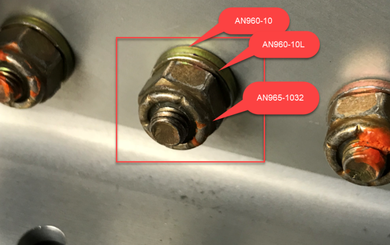
One final comment... regarding the application of thread marking compound to the nuts/bolt-threads.

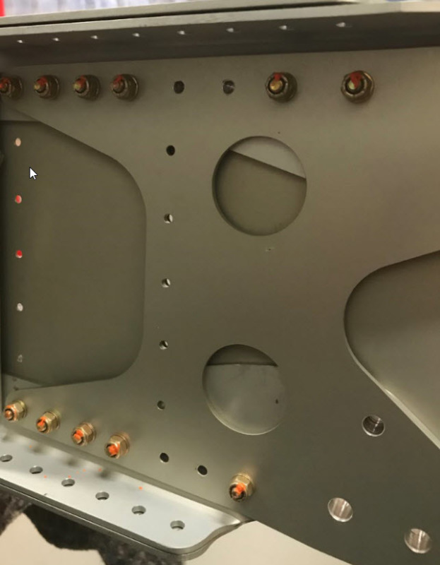
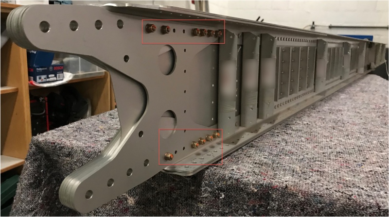
The way the marking compound is applied in Your photos is NOT aircraft standard. Marking compound is intended to show relative movement between parts that is undesirable.

Per Your photos: the marking compound was applied across the side/top of the nuts and onto the tip-top [end] of the bolt thread protrusion. This is inadequate, since this will only reveal whether the nut turns relative to the bolt.

Thread marking compound should be applied between the tip-top of the bolt-thread protrusion, across the top and along-the-sides of the nut, along the side/shoulder of the washer(s) and onto the surface of the structure... in one long/smooth line. This procedure will positively indicate ANY relative movement between the structure-washer-nut-bolt [side-to side or rotational looseness], in-service.

Regards, Wil Taylor

o Trust - But Verify!
o We believe to be true what we prefer to be true. [Unknown]
o For those who believe, no proof is required; for those who cannot believe, no proof is possible. [variation,Stuart Chase]
o Unfortunately, in science what You 'believe' is irrelevant. ["Orion", Homebuiltairplanes.com forum]
 
Thanks for all replies [smile]
WKTaylor said:
Suggest checking specs out for AN3-thru-20 VS the close tolerance version of the same bolt design AN173-thru-186.
Also with AN173 I would have sloppy holes:
AN173: 0.1885 - 0.1895 inch
Predrilled holes: 0.1900 - 0.1950 inch

AN173 is not available as oversize (-X), but NAS6603 is: 0.2016 - 0.2026 inch.
I could use a 0.2026 reamer and manual ream the holes.

What would be the disadvantage by using a 0.2026 reamer, NAS6603-16X bolt, AN965-1032 (tension) nut and use the default torque value for AN3 10-32 (20 - 25 incl/lbs)?

I appreciate your experience and help to find the best possible solution which I can present to the kit manufacturer and ask for final approval.
 
BTW... Your nut appears to have the wrong PN... AN965 ut spec does not exist.

I suspect Your nut is probably an AN365 or MS20365. The 'nominal' replacement for both of these nuts is the all-metal MS21042-3 or L3 light weight low height shear-tension nut.

IF You are serious about changing hardware...

NAS6603-*X requires the hole to be close reamed to 0.2031 [+/-0.0005]. Ensure the reamer has a 0.189-Dia pilot so You get a straight-ream thru the old holes.

CAUTION.
IF You ream hole to 0.2026 You might actually have trouble installing bolts... too-tight fit. Reamer size I cited [with good technique] will make holes VERY close-tolerance and close-in-size to each other for consistent/tight fastening. IF You went to protruding tension head Hi-Loks pins, I would ream the hole size to transition/net-fit 0.0201+/-0.0010

CAUTION: IF 1OS shank protrudes slightly thru the structure [as-it should, especially longer bolt grip], You WILL have to drill/ream-oversize the ID's of Your standard AN960 or NAS1148 washers.

Also... don't forget to break the sharp edges of holes... especially where head will seat... to avoid the sharp edge of the hole conflicting with the bolt head-to-shank fillet radius.

Regards, Wil Taylor

o Trust - But Verify!
o We believe to be true what we prefer to be true. [Unknown]
o For those who believe, no proof is required; for those who cannot believe, no proof is possible. [variation,Stuart Chase]
o Unfortunately, in science what You 'believe' is irrelevant. ["Orion", Homebuiltairplanes.com forum]
 
Thanks again

WKTaylor said:
AN965 ut spec does not exist
Sorry typo, should be AN365

WKTaylor said:
IF You went to protruding tension head Hi-Loks pins, I would ream the hole size to transition/net-fit 0.0201+/-0.0010
What would be better in my case: oversize NAS66XX or oversize Hi-Lok?
Which reamer do you mean for Hi-Lok?
 
I vote for HiLok. The installation guidance is available (very detailed) from Hi-Shear corporation (Now LISI)

Just an example, not a recommendation... I haven't sorted out the exact type that you actually need, so I'm attaching the link below just so you know what kind of information you can expect from a Hi-Lok/Hi-Lite datasheet:

Note 4: Hole preparation per NAS618.

I don't have a copy of NAS618, but WKTaylor's numbers above look right. You can get the specific hole size requirements from LISI/Hi-Shear.

STF
 
I have a hard time understanding the amount of detail that this thread has accumulated .. I believe that we have lost sight of the forest due to the trees .. The original question was about .010 slop in a HOMEBUILT aircraft spar fasteners. I suspect this wing will not see more than 20 hours a year and never see any loads approaching yield. - yet we are ready to redesign this assembly for Mach 2.
I have seen this same thought - process in the OEM repair office. Majority of the time - the damage had to be repaired 'above & beyond' the original design criteria. We had the loads .. a damaged stringer could withstand the loads 'as is' - but nope .. we had to cut it out & splice in a new segment. Fuselage scratch 'good as is' (blended & finished) nope! had to cut it out and install a repair Doubler - removing systems to gain access & drill over 100 new hole in damage tolerance structure. & this was acceptable! Sometime we should just slow down a bit and think about it .. just my 2 cents.
 
edmeister said:
I have a hard time understanding the amount of detail that this thread has accumulated .. I believe that we have lost sight of the forest due to the trees .. The original question was about .010 slop in a HOMEBUILT aircraft spar fasteners. I suspect this wing will not see more than 20 hours a year and never see any loads approaching yield.

this is the classic problem are the guys who designed this idiots or genius i.e is this my failure to understand or theirs to design adequately.

How do you know its going to be only 20 hrs a year, you simply can't, it could just as easily do several hundred hrs a year overloaded (because they often are) in a region with worse than normal gust profiles (gusts in Oz are worse than the US etc etc).

From a GA perspective AN3s in a spar is just a "No". Yes plenty of homebuilts get away with AN3 but with the costs of homebuilt aircraft why not put $50.00 worth of fasteners where it matters. The wing root will likely never be inspected, & 0.010 slop is just as likely break any surface protection before considering cracking. I look at at that first pic and the question that comes to mind is how did they cut the H plate because those other older homebuilts that do have AN3s in the spar probably didn't also put them though laser or abrasive jet cut parts (that may have not had the edge manage removed).

OEM repair offices don't tend to be staffed by their best and brightest.
 
edmeister,
I sympathise.
Someday I may build a homebuilt of my own and I'll be faced with a similar choice. To use the specified "just OK" bolts that are not much better than the ones at the hardware store, or to pay for "good bolts" that I know I can trust. This is the spar root (yes a shear joint but there are other issues) and I wouldn't scrimp here. If it were the bolts that hold the navigation lights on, then yeah, that's what AN3's are for.


STF
 
Status
Not open for further replies.
Back
Top