Eng-Tips is the largest engineering community on the Internet

Intelligent Work Forums for Engineering Professionals

  • Congratulations waross on being selected by the Tek-Tips community for having the most helpful posts in the forums last week. Way to Go!

AN3 hole tolerance question 3

Status
Not open for further replies.

PJYDE

Aerospace
Feb 26, 2018
20
0
0
NL
hi all,

I'm working on the wing spars of a 2 seats light kit airplane.
The spars are already drilled and assembled by the factory.

Here an image of the root part:
2018-02-26_10-04-29_sodxkl.jpg


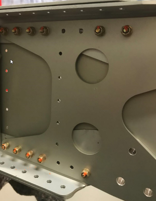
I found out that the thread-lock-paint on some AN3 bolts was broken, so I wanted to re-torque them.
But I was surprised that the bolt had quite some play in the hole.
The bolt has a dia of: 0.1870 inch
The holes vary from 0.1900 to 0.1950 inch
Is this too much?

I though about going to a NAS6603-16 bolt because they are a bit thicker: 0.1885 to 0.1895 inch.
But these are shear bolts and have a shorter thread, so it will be difficult to use a standard washer and AN365-1032 nut and still have 1 to 3 threads protruding.
Are these joins in shear or tension?

What would be the best solution?

Many thanks for your advice.
 
Replies continue below

Recommended for you

edmeister said:
I suspect this wing will not see more than 20 hours a year and never see any loads approaching yield. - yet we are ready to redesign this assembly for Mach 2.
To answer those questions about time:
- 100 hours / year
- 25 years in service

About max loads:
- 700 kg mtow
- limit load factor: normal category -> 3.8
- safety margin: 1.5?
- wing span 9.2 mtr - fuselage: 4 mtr wing span
Very rough calculation: 700 kg * 3.8 * 1.5 = 3990 kg total / 2 => 1995 kg per wing
Assume avg load half way on the wing = 2 mtr moment => 4000 kg on joint (8800 lbs)

Wing spar is attached to fuselage with 8 AN6 and 2 AN5 bolts
Wing spar H doublers are attached to the wing spar with 13 AN3 bolts
Both the AN6 as the AN3 have around 0.004 - 0.008 inch slop.

AN3 bolts have a yield tensile strength at root of 1690 lbs
Multiplied with 13 bolts = 21.970 lbs
But how does the slop impact this tensile strength???

Another thing I found out is that some AN3 holes are crooked.
So reaming to a close tolerance bolt/hi-lok will not fix that problem, probably only make it worse; since now the bolt can settle straight due to the slop in the hole.

I don't want to overthink this situation, sure no need to design this for mach 2.
Although it should be airworthy and stay airworthy.
And; I want to be proud of the result after spending quite some time and money on this project.
 
jgKRI... it's a durability/fatigue issue.

PJYDE... homebuilt construction quality is a personal issue to me.

I helped my dad build his Thorp T-18 N455DT 1967-to-1971 under the oversight of John Thorp. JT was a very detail oriented engineer. I learned a lot about engineering and aircraft construction. He is the reason I changed course from wanting to be a professional pilot [like my dad] to becoming an aero-engineer.

Here is why this is personal.

go to WKTaylor thread posted 31 May 17 19:34... and the very next thread-reply by itsmoked with a photo of T-18 N193N [which tied directly into my previous thread-post].

BTW off-90-deg angle holes can/should be straightened. Will require drilling/reaming using drill-guide block to re-establish [force] the hole to turn perpendicular... and maybe a 2OS [*Y] hole/fastener install, too. From the photos, I would not be surprised if You have adequate margin to step-up the holes to 1/4-Dia nom for close-reamed install [NAS6604, NAS6204].


Regards, Wil Taylor

o Trust - But Verify!
o We believe to be true what we prefer to be true. [Unknown]
o For those who believe, no proof is required; for those who cannot believe, no proof is possible. [variation,Stuart Chase]
o Unfortunately, in science what You 'believe' is irrelevant. ["Orion", Homebuiltairplanes.com forum]
 
If this joint was designed as a friction joint, and not one relying on the shear capability of the fasteners, why do slightly oversize holes matter?

As with most bolted joints, I have to imagine that any relative slip between these parts constitutes a failure of a joint; as a result, the tension applied by the bolts should be enough to prevent relative movement of the parts.

Disclaimer.. not attempting to challenge the expertise of those more experienced with aerospace system design... just trying to find out if there's something to learn here (for me).

From first principles of engineering, it looks to me like that joint was designed to be slip-critical and use fastener tension to maintain joint integrity, in which case the size of the holes doesn't matter much (within reason).
 
WKTaylor said:
Here is why this is personal.
go to WKTaylor thread posted 31 May 17 19:34... and the very next thread-reply by itsmoked with a photo of T-18 N193N [which tied directly into my previous thread-post].
Bizar story, thanks for sharing!

I'm not gonna change anything on this kit before 100% approval of the kit manufacturer.
They tell me not to worry "there was never a problem with this design", but I do worry and many posts in this thread confirm my worries.
It feels like dead end.
 
I'd be pretty annoyed if I designed a kit and then someone started tinkering with it thinking it wasn't up to the job. Especially if they were not even sure if the connection was designed to work as slip critical or bearing.

All this talk of changing someone else's design makes me twitchy, especially on something as safety critical as a wing root!
 
that's why home-builts are owner-builder ... he who builds it takes responsibility (with very limited oversight) for it.

back to the original question ... I don't think it is the end of the world; there are simple things to do to lessen the clearance. We aren't told about the entire joint ... maybe the other holes are "better" ? so it's hard (IMHO) to recommend action, other than possibly talking to the kit designer.

another day in paradise, or is paradise one day closer ?
 
RandomTaskkk, jgKRI...

"All this talk of changing someone else's design makes me twitchy, especially on something as safety critical as a wing root!"

Unfortunately, PJYDE, has already stated that there is no hole size/tolerance data on the plans or with the kit [info manual... or referenced-to... etc]... a glaring deficiency in any aircraft design/plans/kit. I would be astonished [in a bad-way] if the designer left these details to 'Joe-the-assembly-guy'.

I could easily accept this element IF there was specific reference to authoritative established data such as AC43.13-1 and AC43.13-2 or FAA-H-8083-30 and -31V1 and -31V2, or any number of commercial or military structural maintenance/assembly manuals. Important details such as hole-sizes for various type fasteners, installation torque-values, cotter-pinning and safety wiring, etc should never be left to 'good judgment and experience'.

But lets get back to basic data, such as the photos: I have remarked on a just a few of the [bigger] issues that are evident, or suggested, in the photos, which are inconsistent with good quality assembly. There are several other lesser quality issues in the photos that also bother me.

A rule of thumb I developed years ago is this. Workmanship trumps design. A poor/marginal design can be made 'better' [good-enough] by good quality workmanship and careful attention to details. However, a highly competent design can be rendered marginal/unsafe by poor quality workmanship and inattention to details.

My dad had a phrase for good workmanship... 'we're doing it the way John Thorp designed it... for 'MOM'.

Regards, Wil Taylor

o Trust - But Verify!
o We believe to be true what we prefer to be true. [Unknown]
o For those who believe, no proof is required; for those who cannot believe, no proof is possible. [variation,Stuart Chase]
o Unfortunately, in science what You 'believe' is irrelevant. ["Orion", Homebuiltairplanes.com forum]
 
I understand that point of view, and it is sensible.

What makes my eye twitch is what appears to me to be a lack of deeper thinking- the changes being discussed appear to me to make this interface much stronger and/or stiffer; on the face that's a good thing. But what unintended effects does that potential increase in stiffness in this joint impart to other parts of the airframe? What loads will now be transferred that wouldn't before?

Again, I don't design aircraft.. but on the things I do design, I have spent a couple thousand hours of my career rolling back changes that other people, such as service technicians who "knew better than the pointy headed engineer", made without an eye to consequences on the rest of the system. These changes, in my experience, can often cause failures which are very predictable, and point to why things weren't done that way in the first place.

The difference between what I do and what we're talking about here, is that a catastrophic failure for me usually results in some company losing a couple days of production as opposed to one or more people dying a grotesque death.
 
rb1957 said:
different question, what's happening at the four holes in the middle of the web (shown in the box) ?
looks like the outer plate is not well supported ??
Here the first rib will be attached with 5 rivets, not through the whole spar but only through the outer plate.
The upper and bottom hole of that rib will be attached with the same AN3 bolts through the the complete spar.
Furthermore a tank-attach-bracket with be attached with 2 AN3 bolts.
So in total there will be 15 AN3 bolts through the whole spar.
 
Those holes are most likely for the root rib. The OP never did tell us what the aircraft was.
B.E.

You are judged not by what you know, but by what you can do.
 
ok, a rib flange could sit on the outer surface, but there doesn't look to be enough room to install rivets/fasteners ?

but NP ... we're not seeing the entire design and the questions being asked are sensible.

another day in paradise, or is paradise one day closer ?
 
Since we are still on this same subject. Here is another aspect yet to be mentioned (perspective of the Mfr). From the image - it appears that all the hole are pre-drilled in the factory & the home builder just installs the fasteners.
-Typically (in critical situations) a hole would be inline-drilled thru the assembly layers - & not each part separately drilled. So one can see the manufacture's dilemma 1/ jig/assemble the unit / drill / separate parts & finish each individual hole (& maintain the grouping of the parts during finishing & shipping) .. or 2/ Drill all the holes separately while fab'ing the part + Finish the holes & alodine/anodize the parts ..or 3/ have the home-builder drill these 'critical' holes & have no control with the end result.
-In summary - I believe the Mfr optimized the Kit Quality by allowing a minor tolerance so all the parts are 'interchangeable*' and eliminating any error by the home-builder having to drill his own holes. (*interchangeable => Mfr will fab numerous kits at the same time does not have to group 'custom' drilled assemblies) If all the holes were inline-drilled with a given tolerance - then yes .. I can see some 'play'. But given the number of fasteners & the holes not inline drilled a proportion of the 'play' will be eliminated - due that some number of fasteners will always be in bearing.
-One last final note - if Mfr had holes drilled individually with no tolerance; 2 issues are foreseen. 1/ Bolt would never fit through the numerous layers (due to mfr error in machining) & 2/ if the bolt get 'hammered' in - we now have preload .. & also hole damage & the finish coating in the holes gets removed (by hammering the bolt or drilling the hole)
 
possibly mfr drilled the holes in one operation, with the spar assembled ?

possibly the mfr drilled undersized holes, for the builder to expand.

I'd've thought the mfr would have drilled mostly pilots (holes).

another day in paradise, or is paradise one day closer ?
 
All...

RB... RE the initial thread photo. The 4-drilled-holes in-vertical line with gap in-between was a detail I also noted and was concerned about. I am also concerned RE the fit-up gap between the 2-flanges of the upper spar-cap: if the parts are as thick as they seem, may be impossible to hand-pull-up-the-gap... shimming should be required to prevent shanking or excessive pull-up forces.

NOTE.
I suspect there are matched-hole templates [or an equiv CAD/CNC set-up] that established the hole locations/size for each-of-these parts... which were then brought-together and fastened ‘as is’.

NOTE.
The unique matched-hole-tooling methods established by John Thorp [1960s] established the practice ~as follows: locate the hole centers [center-punch] from the flat-pattern templates [FPT]; then pilot drill the actual part one-size under [for 1/8 rivet, drill 3/32 or #40]; then Cleco together [3/32] the structural details [into a major Assy]; then mate drill to #30 and swap Clecos to 1/8 as-we-went; then dis-assemble & deburr and apply primer; then re-assemble with final size Clecos; then final assemble with rivets. The matched-hole Assy practice was ingeniously tooling/jig-free but always required finish-drill [and ream for bolt-holes] of the temp-fastened ‘self-jigged’ structure to ensure mate-drilled/located hole center thru the stack-up. Even then, we occasionally had to step-up a few ‘wild-holes’ OS to get clean alignment thru the stack. BTW, the master-tooling guy who worked for JT, Vaughn Parker, often had to repair FPTs when ham-fisted builders [not me] damaged edges or holes etc. This job kept him busy, when he wasn’t assisting builders coming/going from the Burbank CA shop.

NOTE.
I have posted several times on homebuiltairplanes.com forums, regarding fasteners, materials and metal fabrication/Assy procedures. It seems these topics often generates emotional responses because they are hands-on/personal to those doing the building/assembly... 'gitter-done-good-enough' is an underlying philosophy since $$budgets and time are limited. I get it... Dad/I learned the hard way the true meaning of the [not-so-funny] John Thorp truism: "80% done! Only 50% more to go!!" My +40-year engineering and hands-on experience/opinions have not been well received there [maybe it’s just me/my style]... so I have decided to focus my energy into Eng-Tips.

NOTE.
Years ago I found an informal/funny/well presented ‘Shop Awareness Briefing’ handout that helped explain the implications of assy practices/workmanship to mechanics in-relationship to the real-world element of aircraft structural durability/life. See attached. This ‘document elegantly describes the implication of workmanship discussed here... pictures are worth thousands or words.

Regards, Wil Taylor

o Trust - But Verify!
o We believe to be true what we prefer to be true. [Unknown]
o For those who believe, no proof is required; for those who cannot believe, no proof is possible. [variation,Stuart Chase]
o Unfortunately, in science what You 'believe' is irrelevant. ["Orion", Homebuiltairplanes.com forum]
 
that doc looks like it comes from MD but that typeface looks like Boeing (as in their structures manuals)

another day in paradise, or is paradise one day closer ?
 
WKTaylor said:
See attached. This ‘document elegantly describes the implication of workmanship discussed here... pictures are worth thousands or words.
Many thanks for sharing this document.

WKTaylor said:
I am also concerned RE the fit-up gap between the 2-flanges of the upper spar-cap
No shim is needed because the skins are riveted through the upper layer, the second layer has larger holes so that the tail of the rivet fits in and can be pulled.

You stated in one of your previous replies that you don't like AN3 in a spar and prefer AN173.... or NAS66.... or even better Hi-Loks.
Would you be so kind and briefly explain why Hi-Loks would be a better choice?
 
"why Hi-Loks would be a better choice" ... hole fill

"the skins are riveted through the upper layer, the second layer has larger holes" ... if the skins attach to the outer flange, what does the inner flange attach to ?

another day in paradise, or is paradise one day closer ?
 
Status
Not open for further replies.
Back
Top