Continue to Site

Eng-Tips is the largest engineering community on the Internet

Intelligent Work Forums for Engineering Professionals

  • Congratulations pierreick on being selected by the Eng-Tips community for having the most helpful posts in the forums last week. Way to Go!

analyse of multi bays braced frame

Status
Not open for further replies.

ap3120

Student
Jun 22, 2021
8
I'd like to get the axial forces in a pinned supported 3 bays braced frame. The frame height is h=8m and the width of one bay is L=7 m.
frame_vi7lwz.png

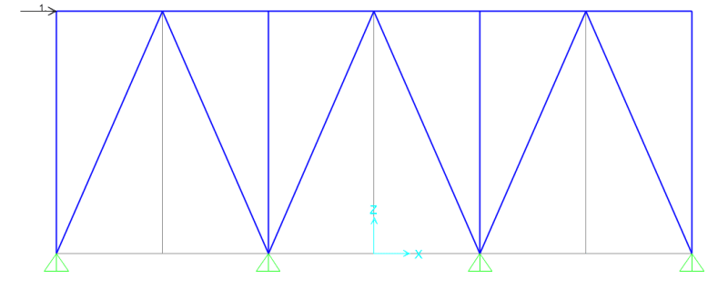
There is only one point load of 1 kN applied on the top left corner.
I'm trying to get the reactions at the supports, but I don't know how to do that. I've also modelled the frame on SAP2000, and I don't quite understand the results (see image here):
frame2_ijoiwa.png

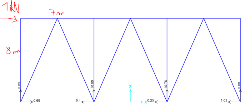
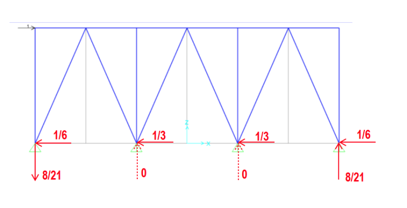
The horizontal reactions make sense cause the sum is equal to the applied loading : -0.69+0.4+0.25+1.03 = 0.99 kN.
However, if I take the moment about the first support on the left for example, I get:
1*h-10.85*L-10.76*2L-6.88*3L = -363.07 kNm different from zero.
So I must be missing something here, and I'd really like to understand how to solve this by hand.

Thanks for your help.
 
Replies continue below

Recommended for you

Unless you are considering axial deformation of each member, why wouldn't each inverted "V" resist one third of the applied force?

Considering a single inverted "V", with a load of 1/3, the horizontal reaction is 1/6 and the vertical reaction is (1/3)*8/7 = 8/21.

image_czw0gd.png


BA
 
If you wish to consider axial deformation of the members, you will need to know the area and Young's Modulus of each.

BA
 
BAR- That may be a valid approximation but I bet the first bay takes most of the load. OP- I think here's no force in the first vertical, and there should net zero vertical force on the thing at the supports.
If this is pin jointed everywhere then I get Bay 1 as the only active member , in fact the only bars of interest are the first horizontal, and the first two diagonals.

Cheers

Greg Locock


New here? Try reading these, they might help FAQ731-376
 
Hi Greg,

I agree that the first bay takes more than one third of the load and the middle bay takes more than the last bay, but without knowing the AE value of any of the members, we cannot tell how much each bay takes.

The key is the top horizontal member. If it is very stiff, the three bays share the load almost equally because they all deflect horizontally about the same amount. If it is very limber (soft, pliable, flexible), the first bay, as you suggested, takes the majority of the load.

With the given load, none of the vertical members takes any load. The top horizontal member takes a variable load with maximum of 1 kN at the left end and a minimum of zero at the right end.

BA
 
I'd expect uplift on the first vertical, down on all the others, no load in any of the verticals, and no load in the last horizontal

Cheers

Greg Locock


New here? Try reading these, they might help FAQ731-376
 
Neglecting second order effects (axial deformation) the red figures show the support reactions. The green figures show the force in the member (tension +, compression -).

If axial deformation is included, the forces will change slightly.

image_bsqc4n.png


BA
 
GregLocock said:
I think you'll find there's a vertical reaction at all 4 of the ground nodes.

That is true, but the vertical reactions can't be evaluated without member properties because the structure is indeterminate, which means it can't be solved by statics alone.

BA
 
Thanks for your replies. You can assume EA constant in all the members. BA, your reactions at the support make sense to me, but are you using a method to find them, or do you just make an assumption? And why wouldn't the two internal supports take any vertical reaction?
Also, I'm not interested in deformations so far, only the axial forces in the members.

Anthony
 
ap3120 said:
You can assume EA constant in all the members.

Okay, that allows the problem to be solved precisely.

ap3120 said:
BA, your reactions at the support make sense to me, but are you using a method to find them, or do you just make an assumption?

The reactions are based on the assumption that the top horizontal member is sufficiently stiff so that each bay takes one third of the lateral load. In other words, I am neglecting the strain in the top horizontal member in order to make the structure statically determinate. It is a similar technique to neglecting axial strain when calculating the reactions of a rigid frame, using hand methods.

ap3120 said:
And why wouldn't the two internal supports take any vertical reaction?

They would, but it is a secondary effect, or at least I believe it is. I have not gone through the calculation for the indeterminate structure. We can do that, if you wish.

In academia, a pin support means zero moment and zero translation. In practice, foundations do not behave as pin supports. Whether they are piles or footings, they rely on soil support, which is unpredictable. If three braced bays are required to resist the applied load, a structural engineer would likely assume that each bay was capable of resisting one third of the load. Alternatively, he could brace a single bay so that it was adequate on its own.

ap3120 said:
Also, I'm not interested in deformations so far, only the axial forces in the members.

Unfortunately, you cannot find the axial forces in a statically indeterminate structure without ensuring that the deformations are compatible.

BA
 
A typical braced bay will deflect as shown on the sketch below. A force H applied to the apex results in a deflection of 27.75H/AE (see below). That is a measure of the stiffness of each bay, taken separately.

A horizontal member with axial force F and length L will strain FL/AE, in this case, 7F/AE.

With that information, it should be possible to write compatibility equations in order to determine all forces precisely.

image_qk3wik.png


BA
 
Thanks for your reply BA.
The example you provided in your last reply, how does it work if I have several bays? And if I consider deformation, would that mean the vertical members would also take an axial load?
 
The highest axial force seen in any diagonal member is 560N. Your SAP2000 result is rubbish, it defies commonsense. If the first diagonal is in tension, then there is uplift at that node, and obviously the compression in the second diagonal is equal to that, but greater than the tension in the third diagonal. Hence there must be a downward force at the second node on the ground. Your first two nodes seem to have the same sign.


Cheers

Greg Locock


New here? Try reading these, they might help FAQ731-376
 
ap3120 said:
BA[/color]]Thanks for your reply BA. You are welcome.
The example you provided in your last reply, how does it work if I have several bays?
If you have 3 bays, assume horizontal forces of X, Y and Z in each bay respectively. One equation is X + Y + Z = 1000N. You have two expressions for deflection (see sketch below), so equate them and solve for X, Y and Z.
And if I consider deformation, would that mean the vertical members would also take an axial load?
No!! By inspection you can see that they carry no load because there is nothing to resist a vertical force where they meet the top chord.

image_bw6isp.png

[highlight cyan]
Note: The last term in the fourth line is incorrect. It should read kX - c(2000 - 2X -Y). It was changed in my next post.[/highlight]

BA
 
I had an error in the last term, which I have corrected below.

As expected, the force taken by each bay diminishes from left to right when the stiffness of the top member is included in the analysis. If the top member was increased in area, the difference would be less, but would still be evident. As it is, the first bay carries almost half the applied load.

Reactions may be readily calculated, but I have not included them.

image_i8nbc8.png


BA
 
Yes, indeed there is something wrong in my SAP model.

Thanks for your reply BA, I just don't understand how you get the last line "horizontal deflection @TC", and how to you get c = 7/EA ?
 
1. c = 7/AE

Strain in the top chord can be expressed as FL/AE where F is the axial force and L is the length of the member. For a typical interior panel, L = 7m, so strain = 7F/AE or cF where c = 7/AE. When F is compression, strain is negative.

2. Horizontal deflection at top chord

Let Points A, B and C be the middle of each of three bays.
Point A deflects kX.
Point B deflects kX - strain in AB = kX - c(1000 - X)
Point C deflects kX - strain in AB - strain in BC = kX - c(1000 - X) - c(1000 - X - Y)

There are two compatibility equations, one for Point B and one for Point C. These, combined with the equilibrium equation (X + Y + Z = 1000) provide the solution to the indeterminate structure, 3 equations for 3 unknowns.


BA
 
Status
Not open for further replies.

Part and Inventory Search

Sponsor