Hi,
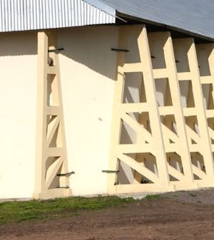
I'm in the early stage of the design of a precast concrete truss... actually a counterfort (see reference [red][sup][3][/sup][/red] for an example). My initial goal was to investigate which arrangement, of all the known truss configurations and their combinations resulted in the fewest tension members for my load case (see [red][sup][1][/sup][/red] for a starting point).
For analysis purposes I couldn't model it as a pure truss, ideal case in which we have axial forces only, no shear, no flexure. One reason is that it's not easy to implement hinges at every node as pure trusses mandate. The other reason is that I assume the same section for concrete chords, struts and diagonal members, so no moment release at the elements' endpoints either.
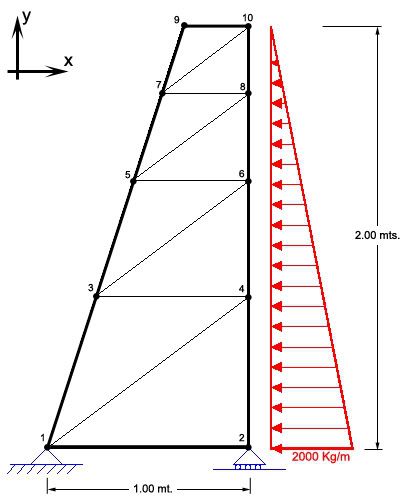
Having said that, I started the iteration with the truss seen below:

And then I got stuck. The forces (axial, shears, moments) are very very sensitive to variations of E.I [red][sup][2][/sup][/red] and the problem is that I don't yet know what the final "I" will be. I just had to pick a tentative "I" to proceed with the analysis, which might or might not end up being the design E.I.
I found that minor increases or decreases in "I" give completely different results. Even the sign of some axial forces are different!
So my question is: How can I arrive at a truss design with the fewest tension elements when I have such a tight dependency on an unknown (cross section) and not so much on the arrangement of the elements per se?
To add to the mess, if I swap the restraints at nodes 1 and 2 I get a whole different set of results in terms of the magnitude of the forces and signs.
Opinions appreciated.
Thanks.
[red][sup][1][/sup][/red]
[red][sup][2][/sup][/red] Which is obvious for statically indeterminate structures.
[red][sup][3][/sup][/red]

I'm in the early stage of the design of a precast concrete truss... actually a counterfort (see reference [red][sup][3][/sup][/red] for an example). My initial goal was to investigate which arrangement, of all the known truss configurations and their combinations resulted in the fewest tension members for my load case (see [red][sup][1][/sup][/red] for a starting point).
For analysis purposes I couldn't model it as a pure truss, ideal case in which we have axial forces only, no shear, no flexure. One reason is that it's not easy to implement hinges at every node as pure trusses mandate. The other reason is that I assume the same section for concrete chords, struts and diagonal members, so no moment release at the elements' endpoints either.
Having said that, I started the iteration with the truss seen below:

And then I got stuck. The forces (axial, shears, moments) are very very sensitive to variations of E.I [red][sup][2][/sup][/red] and the problem is that I don't yet know what the final "I" will be. I just had to pick a tentative "I" to proceed with the analysis, which might or might not end up being the design E.I.
I found that minor increases or decreases in "I" give completely different results. Even the sign of some axial forces are different!
So my question is: How can I arrive at a truss design with the fewest tension elements when I have such a tight dependency on an unknown (cross section) and not so much on the arrangement of the elements per se?
To add to the mess, if I swap the restraints at nodes 1 and 2 I get a whole different set of results in terms of the magnitude of the forces and signs.
Opinions appreciated.
Thanks.
[red][sup][1][/sup][/red]
[red][sup][2][/sup][/red] Which is obvious for statically indeterminate structures.
[red][sup][3][/sup][/red]

