Continue to Site

Eng-Tips is the largest engineering community on the Internet

Intelligent Work Forums for Engineering Professionals

  • Congratulations SE2607 on being selected by the Eng-Tips community for having the most helpful posts in the forums last week. Way to Go!

Analysis of Multi-Bay Portal Frame

Status
Not open for further replies.

RaptorEIT

Structural
Feb 7, 2019
34
I have a three bay, rigid, plane frame that I am analyzing for a rolling 50 kip vertical load. The frame has pin connections at the base. I am trying to figure out how to analyze the three bay frame by hand, but have found very little technical literature on analyzing multi-bay frames other than by approximate analysis. I would like to use the slope-deflection method by splitting up the three bay frame into three simple, single bay frames. Can I separate each bay into its own single bay plane frame, and then superimpose loads similar to the approximate analysis methodology? I realize that I can model this very quickly in STAAD, but I am a new engineer and would like to understand and completely grasp how to perform this analysis by hand before modeling with software.

If instead I used a braced frame system with inverted chevron bracing, would I analyze as a truss system with pin connections, and then analyze with the force method for indeterminate trusses since I would have four external pin connections at the base?

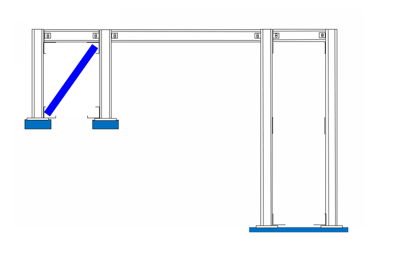
I have attached a simple sketch to help visualize the frame.

Thank you!

 
Replies continue below

Recommended for you

would MDM help, to analyze the horizontal member (a beam on several supports) ?

It looks like all the joints (including the frame legs at the ground) are moment connections ?

Maybe use unit force ? Consider the end bay as a standard portal frame with some moment "leaking out" into the continuous horizontal beam. Then the flip-side of this is the portal frame being loaded by this moment, say 1000ft.lbs. And the same is happening at the other end bay (just opposite).

Or maybe this is the slope /deflection you were thinking of ... solve the end bay, how much does the RH joint rotate, calc moment to resist this, and iterate ?

If you look at the horizontal beam, it has 4 force reactions and 4 moments ... that's a lot of redundancy (6). Two bays would be redundant to 4 dof, and much easier to solve.

another day in paradise, or is paradise one day closer ?
 
Just a word of caution on moment frames w/ pinned bases......you may get excessive lateral drift in your frame. I'd fix at least one of the bases.

I am a big fan of the portal method. It is super simple and gives reasonably accurate results. It assumes an inflection point in the middle of all beams and columns.

Look in almost any structural analysis text or try Google.

 
The moment distribution method is a good method to get accurate results for indeterminate frames. I don't believe the portal method would work for a rolling gravity point load as the inflection point would depend on the location of the load.
 
OP said:
Can I separate each bay into its own single bay plane frame, and then superimpose loads similar to the approximate analysis methodology?

I don't think so. Would the two, unloaded bays, not simply produce no results? Or are you planning to look at each bay individually as though it did carry the 50 kip? Either way, I'm not feeling the superposition thing. I like moment distribution for this as others have mentioned.

For the design of the beam alone, I think that it would be pretty reasonable to just replace the columns with pin/rollers at the points along the beam where the columns tie in. If you wished to extend this, you could then assign the rotations at the tops of the columns to match the slope of the beam at the corresponding locations. This would give you design moments for the columns. All this would likely be as much effort as moment distribution (if not more) and would be less accurate.
 
Thanks all for your replies and suggestions. It looks like I need to learn the moment distribution method, and then apply it to the frame.

If instead I used an inverted chevron braced frame, what method would you suggest to determine the base reactions and axial forces? I assume I could analyze as a truss, but I read that you cannot the slope-deflection method or moment distribution to trusses, as there are no member moments. With all base connections pinned, I would have 8 unknown reactions and only 3 equations of equilibrium. I have used the force method for statically indeterminate, 1 degree trusses, but not for 5 degrees indeterminacy. Any suggestions?

Thank you all.
 
For Chevron, do a method of joints for the axial forces. Then use something like slope deflection or moment distribution to analyze to top member as a continuous beam, treating the Chevron joints as points of vertical support.

Will you be doing a separate analysis for frame lateral loads?
 
there's a difference between trusses with pinned joints and trusses with fixed joints.

inverted chevrons maybe solve all of your questions, depending on how many chervon peaks support the horizontal beam ...
if 2 then statically determinate, if 3 then singly redundant (the horizontal beam that is), etc.

Its easy to solve one redundancy by hand, unit force method is my preference, 3 moment equation would also be easy to apply.

another day in paradise, or is paradise one day closer ?
 
Thanks Celt83, that is a great link that I have referenced in the past.

KootK - I have attached a sketch of the braced frame option. I opted to use inverted chevron bracing to avoid having the lateral braces take a substantial amount of load when the load location is at the beam mid-span, where the bracing would coincide. In the analysis, I placed the 50 kip load at the beam mid-span to design the beam. To design the column and lateral bracing, I placed the 50 kip load directly above one column and then applied a 2 kip lateral load to cover wind and rolling effects. This should give me the worst case loading for each element. I analyzed each "bay" by first finding the external reactions at the base using the force method, and then used the method of joints for the member forces. This seemed simple and straightforward enough, but I was curious as to whether I could isolate each bay in the analysis like I did, or if I had to look at the global structure as a whole to get more accurate results.

Thank you all.
 
 https://files.engineering.com/getfile.aspx?folder=643d0012-7170-4268-834c-de3fe06d0389&file=Braced_Frame_Sketch.docx
Thank you rb1957 for your reply. I agree, unit force method would be my preference also. The braced frame option seemed more straightforward to design, as the lateral load path was in the form of the lateral braces. I was looking into designing a moment frame to ease construction by not having to erect so much bracing, but the lateral load path wasn't as straight forward when using a moment resisting, three bay frame. This lead me to think that maybe I could separate each bay and apply the slope-deflection method, but after hearing all responses it seems like mdm is the way to go.

Again, thank you for your insight.
 
- Obviously, I don't know all of the constraints here but, at first blush, you seem rather over-braced. See my suggestion below.

- I think that a good strategy here would be for you to employ whatever approximate methods make sense to you and then compare those results to FEM output.

C09_scxvof.png
 
thx for sketch.

why not simplify the braced frames to a single diagonal ?

another day in paradise, or is paradise one day closer ?
 
My thought process behind bracing each end bay: I plan to install a pad-eye on top of each end column, and use that as a pull-point to move the load along the frame. Since I am going to have a pull-point at each end, I thought it would be a good idea to have lateral bracing at each end. Is lateral bracing in one bay sufficient for this scenario? The lateral load would travel to the location of the diagonal brace, so that does make sense to just have diagonal bracing in one bay. I was just being conservative since it is a temporary structure installed for a large, moving load.

Thank you
 
sure you can react the longitudinal load at both ends. Just more complicated, particularly given how different the ends are (the shorter one will be much stiffer than the long end).

I can see the logic for making a mid-bay pick-up for the chevron.


another day in paradise, or is paradise one day closer ?
 
It's not really simple, but I have used a moment distribution for a frame in Excel and then automated it with a macro to get the reactions for various loading.
 
Thanks all.

So typically with a lateral force resisting system, you generally need at least one brace system within each plane of a frame. For example, if I was to design a low-rise, four sided square building, I would need at least one braced bay on each of the four sides for the lateral loads, and then some type of lateral bracing for the roof plane. A question I have now is when is it necessary to include more than one braced frame within a single plane? It would seem that the lateral load would generally travel along the first lateral brace it encounters along the load path, with very little leftover for a different braced bay within the same plane. I don't deal a lot with drift limits, since most of my steel structures are just platforms or frames for moving loads, but it seems that multiple braced bays within the same plane of a frame are only provided to limit the inter-story drift. Is this a correct statement? That would make sense why the previous sketch appeared "over braced", because in reality, only one lateral brace system is needed per plane, assuming drift is acceptable.

Thank you for your insight.
 
OP said:
A question I have now is when is it necessary to include more than one braced frame within a single plane?

The need for more frames comes down to this:

1) Is there a need to spread lateral resisting strength to multiple locations? A single brace/footing can only take so much.

2) More importantly, considering P-delta effects, is there a need to spread stiffness along the framing line? At any location, the amount of lateral travel that you'll see in your gravity loads is a function of braced frame drift, elongation in the drag strut, and any slip in your connections. Those add up over long framing lines unbroken by intermittent bracing.

Back before computers, and shoddily trained junior engineers, there was an informal rule of thumb that every fourth framing bay ought to be braced. And don't think that I'm calling you a shoddily trained junior engineer. You may in fact be that but, so far, I've seen no evidence of it. You're here taking the time to ask the right questions which is absolutely everything.
 
Assuming the one brace is adequate to resist the full lateral load applied to the frame, and the beams and connections are adequate to transfer the load from the point of introduction to the braced node, then a single brace should be sufficient. IOW, follow the load path and check each member and connection along the way.

If you have more than one brace, the load will theoretically be distributed based on the relative stiffness of the sum of the components between where the load is introduced and the endpoints of the load path (bottoms of the braces).
 
KootK, I will agree with your statement that I am a "shoddily trained junior engineer". Most of what I have learned has been from reading a textbook. I have had very little mentorship since graduating, and unfortunately, will not have any structural engineering mentorship for the perceivable future. Since we have structural analysis software, it isn't seen as a problem.


It sounds like I just need more practice with indeterminate structural analysis techniques. I never learned moment-distribution method, matrix analysis, or any numerical methods of analysis while in undergrad. It seems like that would be a good starting point for now.

Thank you very much for your help.

Thanks HotRod10 for your input as well.


Status
Not open for further replies.

Part and Inventory Search

Sponsor