Continue to Site

Eng-Tips is the largest engineering community on the Internet

Intelligent Work Forums for Engineering Professionals

  • Congratulations SE2607 on being selected by the Eng-Tips community for having the most helpful posts in the forums last week. Way to Go!

Analysis of Multi-Bay Portal Frame

Status
Not open for further replies.

RaptorEIT

Structural
Feb 7, 2019
34
I have a three bay, rigid, plane frame that I am analyzing for a rolling 50 kip vertical load. The frame has pin connections at the base. I am trying to figure out how to analyze the three bay frame by hand, but have found very little technical literature on analyzing multi-bay frames other than by approximate analysis. I would like to use the slope-deflection method by splitting up the three bay frame into three simple, single bay frames. Can I separate each bay into its own single bay plane frame, and then superimpose loads similar to the approximate analysis methodology? I realize that I can model this very quickly in STAAD, but I am a new engineer and would like to understand and completely grasp how to perform this analysis by hand before modeling with software.

If instead I used a braced frame system with inverted chevron bracing, would I analyze as a truss system with pin connections, and then analyze with the force method for indeterminate trusses since I would have four external pin connections at the base?

I have attached a simple sketch to help visualize the frame.

Thank you!

 
Replies continue below

Recommended for you

OP said:
and unfortunately, will not have any structural engineering mentorship for the perceivable future.

Get that mentorship here. That possibility is one, very fine, aspect of the internet age. There frankly isn't a design office on the planet that can offer the same quantity and calibre of willing mentorship that you can find right here. We'll fight among our ridiculous selves to be the first in line to help you out.

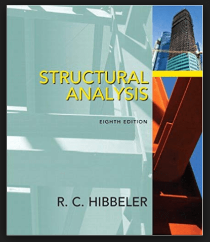
With regard to your analysis method deficiency, consider the text below. It's an easy read and will get you up to speed in a hurry.

c01_f2jizq.png
 
Raptor77R:
this site is fairly decent at presenting some of the analysis methods:

they have a few typos here and there but they convey the concepts decent enough.

For matrix analysis grab a copy of the text book here:
I found I personally learned and retained more trying to create excel spreadsheets for somethings as it forced me to really make sure I understood something to be able to make a generalized calculation spreadsheet rather than just looking up a formula and plugging and chugging.

Edit:
KootK said:
We'll fight among our ridiculous selves to be the first in line to help you out.
:)


Open Source Structural Applications:
 
KootK - Thanks for the reference to Hibbeler's text. I applied the truss analysis using the stiffness method on the single diagonal braced frame sketch you included within a previous post. By inspection, I know that the vertical member framing into the bottom left support is a zero-force member if only a lateral load is present at the joint it frames into above. Therefore, the horizontal reaction at the support should equal the vertical reaction if the bay length and height dimensions are the same. In the analysis, I used a 5' wide x 5' tall bay, so the vertical and horizontal reaction should be equal. Since they are not, the truss appears unstable. The truss has 8 bars, 5 support reactions, and 8 joints, then b+r=13 and 2j=16, therefore it is unstable. With all this being true, how do I go about analyzing the frame? I can added bracing to the right-most bay, but I cannot add bracing to the middle bay due to interferences, and therefore it would appear the truss would always be unstable due to the middle bay.

Do you have any recommendations on how to approach this problem? Is analyzing the frame as a truss not the correct approach? In my mind it should be stable, since braced frames in buildings are constructed in this manner and they have no stability issues.


Celt83 - Thanks for that info. I created an excel spreadsheet also for the stiffness method of the frame. No wonder computers are used nowadays, a 20x20 matrix took a minute to construct [bigsmile]


Thank you

 
when you say "therefore it is unstable" do you mean that it is statically indeterminate (or redundant) ?

the horizontal member is indeterminate, but MDM (or many others) can resolve this.

the frame is determinate for horizontal load (since there is only one loadpath).

I think all this says that you should not consider this as a truss (with axial members only) since there should be an amount of bending in a frame. The horizontal member is definitely a beam.


another day in paradise, or is paradise one day closer ?
 
I am so glad that there is this forum for me to learn. I am only a junior engineer and never licensed. I have about two years of experience. I do not have a mentor. I have to learn on my own after graduation. I only have an senior engineer for three months when I was an EIT. I am a civil and structural graduate. I am more an architectural and structural designer for small buildings.

I think we analysis a port frame of 4 bays using the portal method or the cantilever method. Tall Building Structures, analysis and design by Byran Stafford Smith and Alex Coull has a very good worked out example. For the port frame of 4 bays, the axial forces of the interior columns are assumed to be zero, leaving the column on the windward side in tension while the column on the leeward side in compression. For the cantilever method, the building is assumed to be a deflected cantilever from ground up. However, the Tall Building Structures only has a three bays worked out example for the cantilever method.

The portal method is good up to 25 stories with a height to width ratio not great than 4:1. The cantilever method is good up to 35 stories with a height to width ratio of 5:1.

I could not find any information on chevron trusses except the Seismic Design Manual by the American Instittute of Steel Construction and the Structural Steel Educational Council.

I still feel fuzz in following the worked out examples on the book, so I am only quoting what the book says. But i am not going to design anything falling out of The Canadian Building Codes Part Nine and The American International Building Codes for Residential houses and three storey apartment.

disclaimer: all calculations and comments must be checked by senior engineers before they are taken to be acceptable.
 
OP said:
The truss has 8 bars, 5 support reactions, and 8 joints, then b+r=13 and 2j=16, therefore it is unstable.

I count eight support reactions, horizontal and vertical at all four base plates. That help any?

OP said:
Is analyzing the frame as a truss not the correct approach?

This should work just fine so long as you're applying nodal forces.
 
"I count eight support reactions, horizontal and vertical at all four base plates." ... assuming the uprights carry transverse load (ie in bending, ie not as a axial truss element).

5 support reactions = 4 vertical and 1 lateral, which is what we were trying to achieve with the diagonal member (to react the lateral loads).

"nodal loads" I think means loads above the supports, which is a pretty trivial solution (all the vertical load would be reacted by the one vertical element). More general vertical loads (ie between support nodes) requires the horizontal member to react as a beam (on many supports). But that may have been your point ?

another day in paradise, or is paradise one day closer ?
 
rb1957 said:
5 support reactions = 4 vertical and 1 lateral, which is what we were trying to achieve with the diagonal member (to react the lateral loads).

I disagree and stand by my original numbers. Eight support reactions are available even if some will have zero magnitude. Moreover, ignoring those zero load restraints would lead to instability were one looking at this with FEM software etc. I thought that this might be entering into OP's assessment of instability. Obviously, when working by hand, a confident structural engineer can simplify the problem to not include consideration of the zero force restraints.

rb1957 said:
"nodal loads" I think means loads above the supports, which is a pretty trivial solution (all the vertical load would be reacted by the one vertical element). More general vertical loads (ie between support nodes) requires the horizontal member to react as a beam (on many supports). But that may have been your point ?

My point was really that a truss model is suitable for nodally applied loads and generally unsuitable for loads applied directly to members. That's all. I'm not entirely certain at this point but, given that much of the discussion here revolves around the bracing, the nodal load of interest would be a lateral load. I'll leave it to OP to correct that assumption if necessary.
 
Status
Not open for further replies.

Part and Inventory Search

Sponsor