Continue to Site

Eng-Tips is the largest engineering community on the Internet

Intelligent Work Forums for Engineering Professionals

  • Congratulations waross on being selected by the Eng-Tips community for having the most helpful posts in the forums last week. Way to Go!

Analyzing a Column with Bends

Status
Not open for further replies.

ivanga7

Civil/Environmental
May 20, 2016
40
Hi all,

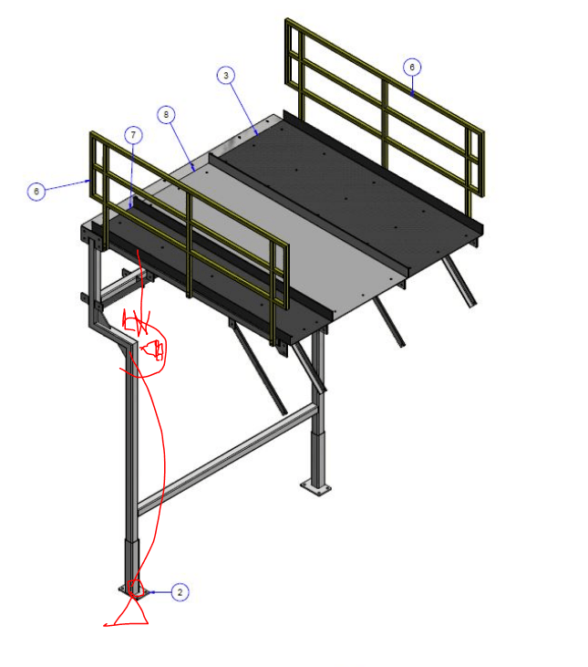
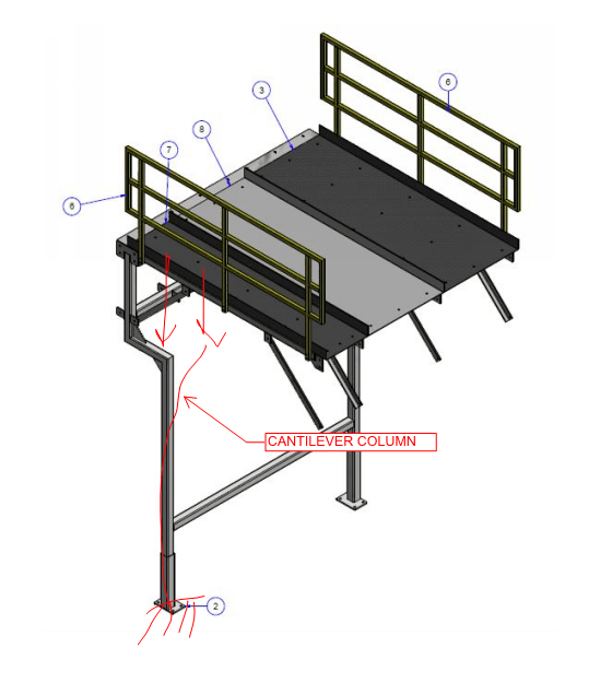
I am working on a project where I have to justify a system of frames that were installed without permits. The frames support a conveyor system and a catwalk that is only used for maintenance. The problem that I'm facing is with the columns because some of them are not straight and have bends (as seen on the attachment). How do I go about analyzing these columns? Can someone point me in the right direction?

Thanks
 
 https://files.engineering.com/getfile.aspx?folder=31defec9-14f1-485f-a789-6c0227789775&file=Catwalk_Column.JPG
Replies continue below

Recommended for you

It seems like fairly first principles stuff? Its just a column with moments? Work out the force x distance and design for combined axial and bending.
 
OP said:
How do I go about analyzing these columns?

With some difficulty I'm afraid. You can use a Matrix/Stiffness analysis with geometric non-linearity included to work out a bifurcation load in a similar, but vastly more complicated manner than we do with ordinary Euler buckling. It's tough so say without knowing more about what's happening in and out of the page but you might also be saddled with a messed up torsional buckling mode as well. Some analysis options:

1) I have a MathCAD sheet that handles this but it's poorly documented and would probably lead you astray.

2) There's some free software called Mastan that you can google that could be used for this.

3) Done carefully, you might be able to use the direct analysis method for this, in conjunction with an ordinary FEM program that handles P-delta.
 
pinned at the base, or fixed ?

lateral shear at the ground, or roller ?

another day in paradise, or is paradise one day closer ?
 
It's pinned at the base with 4 wedge anchors to an existing 6" thick concrete slab
 
I'll handle things like this by:

1) Making some gross but conservative assumptions and seeing if that works then:

2) Refining my analysis and trying again.

3) Rinse and repeat until I get what I need (or give up).

Here're, I'd start with these two simple analyses.

c01_ztrwi1.png

c02_bq8xso.png
 
Shouldn't there be a moment reaction at the base on either case?
 
Only for the second case in my opinion. It's your assignment and therefore your call of course. You know the details better than I.
 
It can't be pinned at the base or it would fall over as previously stated.

If there are only two columns, what is the purpose of Member 1 and the column attachment at the other end of the platform? In that case there is definitely a moment at the base of the two columns.

If there are four columns similar to the two shown, the structure would be symmetrical and the base moment would be small.

BA
 
buttt … we don't know the rest of the structure, nor how this portion attaches to the rest of the world, unless we assume there is in-plane reaction at the walkway, and axial reaction at the little diagonal braces.

maybe the column is simply a column loaded by offset load, maybe there's some component of load inplane (lateral) from the knee brace ?

fore/aft bracing looks a little light.

It may be better to have the platform over-hang the support, and have a "sensible" straight column ?

another day in paradise, or is paradise one day closer ?
 
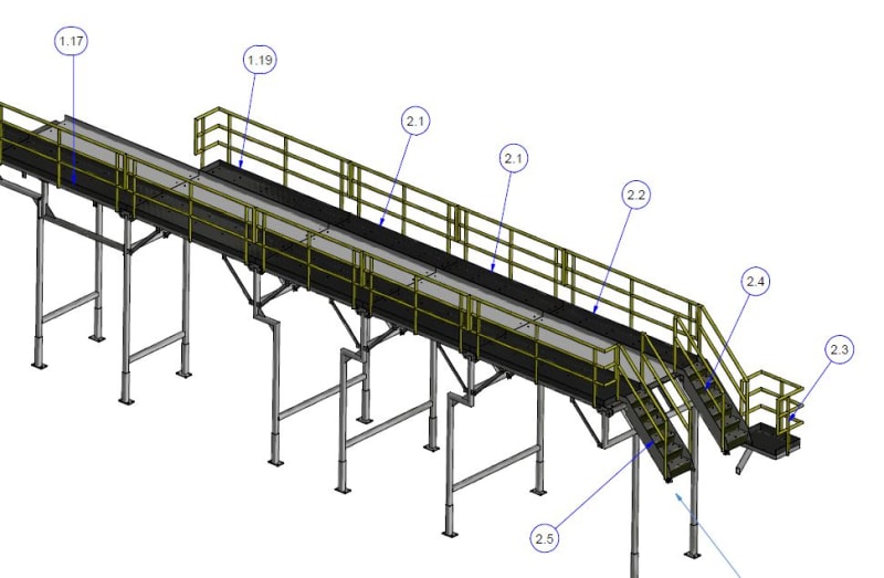
Sorry for the confusion. The structure is composed of multiple segments just like this one. Some are longer, some are shorter but overall it's a similar frame supporting the entire assembly. Maybe this image will clarify.
Catwalk_Platform_3D_jh5goq.jpg
 
It would be pretty straight forward in a structural analysis program that handles P-Delta effects. By hand it looks like a PITA.

Maybe just make the person who signed off on this get up on the walkway while you add concrete blocks to the rated LL. If they report no problems you should be good to go.
 
so there's not much lateral restraint, side-to-side in either direction ?

what's to stop the "dog leg" columns going straight up to the walkway ? I assume they are "dog legged" to clear some space underneath the walkway ?

the only lateral support would be from fixed grounds. can you add diagonal bracing to some bays ??

can you add inplane diagonal bracing, to stiffen the frames fore/aft ??

another day in paradise, or is paradise one day closer ?
 
Yes, not much lateral support. I was thinking of adding some diagonal bracing for lateral loads. I can't really add diagonal bracing for in-plane loads because I would be blocking traffic areas or equipment.

You are correct, the reason for the "dog leg" columns is to avoid some equipment that is in the way.
 
Why the bend to avoid some equipment when they provided knee brace anyway? I should suggest to just make the column straight and knee brace either on one side and check the stresses.
 
Ivanga7:
Abortions are always really messy even if they are only structures which are abortions. This may be a good example of why we shouldn’t allow/tolerate some monkey who has a CAD program pretend they are an engineer. The damn program will allow almost anything to be drawn with little regard for what can practically be analyzed, designed, built and safely used. I’ll bet they couldn’t even have drawn that mess without their computer software, given their lacking level of engineering knowledge and experience. There probably isn’t a real good reason why some beam structural system up at the level of the platform could not be (or had not been) developed which would more easily solve the structural problem than the cranked columns or beam-columns. It seems that three or four longitudinal beam lines up in the platform floor system would have aligned with all of the column bases and avoided the cranked columns.
 
Hello Once the loads and constraints are defined (easier said than done), AISC section 1.6.2 can be used to check safety factor of columns under combined stress. You could start with some simplfying asumptions to see about where you are at.
 
Status
Not open for further replies.

Part and Inventory Search

Sponsor