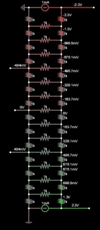
Hiya Sparkies!
I am sure this is going to be a very noob-sounding post, but it's been a few years since my Circuits class...
I have what is essentially a ladder-shaped arrangement of resistors. Each "rung" of the ladder is a resistor, and each segment of the "legs" from rung to rung is also a resistor. I can't disconnect any of the junctions, but I'd like to know the resistance of each segment. I can check the resistance from any junction to any other junction pretty easily, but I know that every measurement I can take is going to end up with a bunch of parallel resistors in the path.
I can't assume symmetry of resistance values on any portion of the ladder, so I am guessing that if my ladder has "n" resistors then I need to take at least "n" measurements, but I don't have a great idea how to set up the measurement points and forumulas/algorithms I should use to do this most efficiently. My fear is that it ends up being a huge system of equations with "n" unknowns, and "n" is in the neigborhood of 30.
The other wrinkle is that I am afraid that variability in my measurements may lead to a system of equations that's un-solvable. The resistance values are (ideally) in the 10s of ohms range. Right now the measurements are taken manually with a DMM, and I can't be entirely sure that if I measure from A to B, then A to C that point A was exactly the same point electrically. At some point I hope to build a jig with multiple probes and switches such that I can take every measurement without moving any probe and just switching the electrical paths. I hope that makes sense... any input or guidance to kick this off in the best direction would be appreciated!

