Continue to Site

Eng-Tips is the largest engineering community on the Internet

Intelligent Work Forums for Engineering Professionals

  • Congratulations waross on being selected by the Eng-Tips community for having the most helpful posts in the forums last week. Way to Go!

Anchor bolts shear transfer

Status
Not open for further replies.

darkjmf1

Structural
Dec 17, 2012
49
Hello,
I am having some concerns regarding the shear transfer mechanism of anchor bolts.

Let's say I have a (real big) pedestal (1400x5400 mm, f'c=25MPa) supporting a base plate anchored by 27M56 (Fu=410 MPa) and resisting a factored shear Vu=3600 KN (see attached sketch).
Code is ACI-318-14.

If we design the concrete section for shear, it results that no shear reinforcement is required. For the sake of minima, let's deploy 2 top layers of #4@75 and #4@300 below.

When designing anchor bolts concrete breakout in shear (Cl.17.5.2), if fi·Vcbg<Vu, you need to provide anchor reinforcement (Cl.17.5.2.9).
If we focus in the failure mode described as Case 2, with the total shear resisted on the rear row of anchors, it results in 4000 mm2 (!!!) for one tie of horizontal reinforcement (distributed within height = le).
I know this is a local mechanism to transfer shear from the anchor bolts to the concrete section, but the resulting reinforcement is a lot for a section supposed to not require shear reinforcement.

What am I doing wrong? Please, help me.
Thank you all.
 
 https://files.engineering.com/getfile.aspx?folder=9d0ce204-3654-4cb5-b6d4-8f6dc8a78399&file=DOC221019-22102019093417.pdf
Replies continue below

Recommended for you

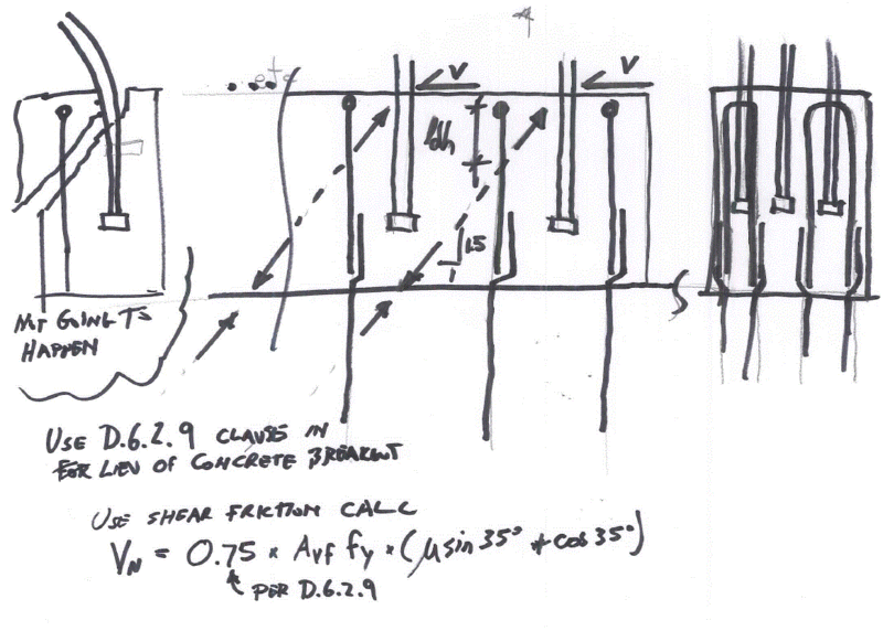
I would look at using the "develop anchor reinforcement on both sides of the breakout surface" clause (D.6.2.9 318-11) and provide stirrups from the surface of the pedestal (left side) into the base. I'd verify the amount of rebar used against a shear friction check per 11.6.4.
 
Teguci said:
I would look at using the "develop anchor reinforcement on both sides of the breakout surface" clause (D.6.2.9 318-11) and provide stirrups from the surface of the pedestal (left side) into the base
But my original concern remains:
How come that a section which is not required to have shear reinforcement is obliged, due to the anchor shear design, to provide such an amount of shear reinforcement?
At least when you calculate a shear reinforcement for the whole section you take into account that the concrete is resisting some part of the shear, but when you design for anchors it seems that the concrete is not resisting anything and is the reinforcement the one that takes it all.
 
You are conservatively assuming ha = 2000. If you consider that the compression struts from the shear plane extend into the base concrete then ha goes to infinity and you can use the larger ca1 value. When you design for shear on the concrete pedestal you are transferring that shear across that plane into the base concrete.

Even so, due to the concentration of shear at anchors and the need to have localized shear friction at the interface, I'd put stirrups in to exclude a sudden brittle failure.
 
Teguci said:
ha goes to infinity and you can use the larger ca1 value
Sure that increasing Ca1 results in a bigger value of Vcbg, but not enough to compensate Vu, so at the end of the day I will need supplementary reinformcement anyway.
And I will have to face my original problem: designing a horizontal reinforcement for the total value of Vu.
 
1) Contrasting the shear capacity and anchorage capacity is interesting. Neat problem.

2) I don't have all the answers here but believe that I do have some. Sadly, I man not have time to critique your actually calculation though (it looks beautifully set out BTW).

OP said:
If we design the concrete section for shear, it results that no shear reinforcement is required.

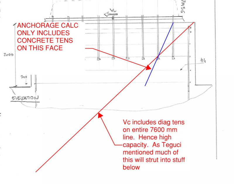
3) The first sketch below illustrates why I think that your concrete shear capacity is coming out so much larger than your anchor capacity.

OP said:
How come that a section which is not required to have shear reinforcement is obliged, due to the anchor shear design, to provide such an amount of shear reinforcement?

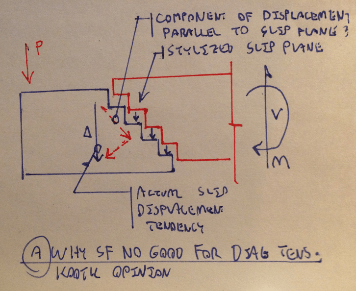
4) The second sketch below is taken from this thread and explains the issue I believe. For post-cracked shear capacity, the movement vector is assumed to be parallel to the shear crack and, thus, you still have functional shear capacity post cracking from aggregate interlock. This is why we can to Vc + Vs. For anchorage, the movement vector is much closer to pure concrete tension than it is pure sliding parallel to the cracked surfaces. This is why, for anchorage, the rebar is assumed to do 100% of the work post cracking.

OP said:
And I will have to face my original problem: designing a horizontal reinforcement for the total value of Vu.

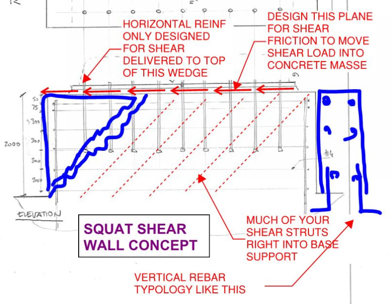
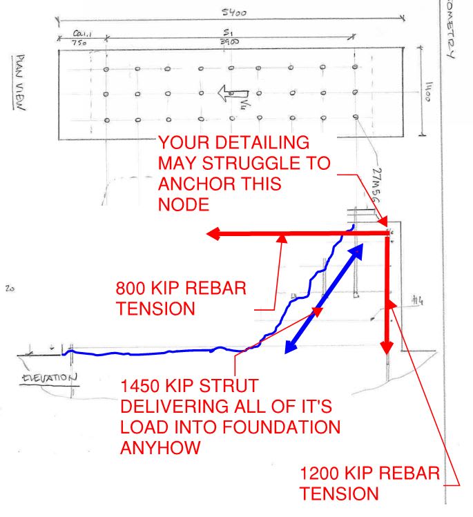
5) If you're willing to stray from conventional anchorage design, you can develop a much friendlier solution using principles similar to what Teguci has mentioned. See the last sketch below where this is treated similarly to the design of a squat shear wall.

c01_pa6jz3.jpg


c02_z6bd1g.png


c05_ogpvw8.jpg
 
KootK said:
See the last sketch below where this is treated similarly to the design of a squat shear wall.
I like that approach but, according to ACI 318 and as said in my OP, the failure mode described as Case 2 assumes that the total shear have to be resisted on the rear row of anchors.
It is my understanding that it does not literally mean the last row, but any other row than the first one.
In your sketch, it could be any row right before the failure surface, so eventually we will have to cope with all the shear within the breakout cone (no help of struts into the base) as in the original situation I presented and therefore the big amount of reinforcement.
 
darkjmf1 said:
...according to ACI 318 and as said in my OP

Yeah, I saw it. I just don't agree with what you said.

quote said:
...the failure mode described as Case 2 assumes that the total shear have to be resisted on the rear row of anchors.

You've interpreted that as a restrictive statement when, in-fact, the code means it as a permissive statement. They're trying to do you a solid by allowing you to engage a larger breakout surface than you'd get if you had to assume load transfer further forward. Nothing of that prohibits you from assuming that the load transfers further forward in the connection if you wish to do that.
 
OK, got my crayon and toilet paper out -

CONCRETE_BREAKOUT_bgzhri.gif


Locking in the concrete breakout cone with rebar developed across the shear plane will require yielding of the rebar or crushing of the concrete.
 
Another way to come at this is to ask yourself how reasonable is my load path if I stick to the rear anchor stuff?

c01_vkuumk.jpg
 
Status
Not open for further replies.

Part and Inventory Search

Sponsor