Continue to Site

Eng-Tips is the largest engineering community on the Internet

Intelligent Work Forums for Engineering Professionals

  • Congratulations waross on being selected by the Eng-Tips community for having the most helpful posts in the forums last week. Way to Go!

Anchor Chair with Continuous Ring Top Plate

Status
Not open for further replies.

ahardy89

Structural
May 26, 2020
15
I am evaluating an steel anchor chair design for a ground supported water tank using AISI T-192 (per AWWA D100). Within AISI T-192, it states if chair height calculated is excessive, a solution maybe to use a continuous ring at the top of the chairs. Minimizing the eccentricity is not possible and the load on the anchors for the chair attachment are pretty high (130 kips) so I am having trouble keeping the localized stresses below the recommended maximum of 25ksi. So it appears using a continuous ring would help reduce the localized stresses transmitted to the shell.

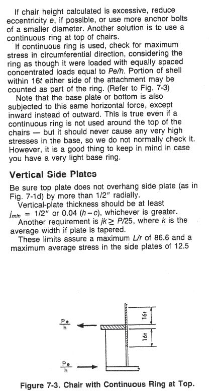
The AISI document states to check for the maximum stress in the circumferential direction (assuming they mean hoop stress), considering the ring as though it were loaded with equally spaced concentrated loads equal to P*eccentricity/chair height.

My question is to evaluate the stresses in the ring:
1. Is the intention that the equally space concentrated loads are applied at each anchor chair around the shell?
2. Is there a formula to calculate the maximum stress in circumferential direction? I know how to calculate the hoop stress using a uniform loading but not sure how to for concentrated loads. Would using Roarks formulas for rings be applicable?
3. I assume I would need to add the hoop stress from hydrostatic load from inside the tank?

If anyone has any similar examples, it would be greatly appreciated.
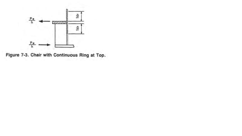
cont_ring_dwnpni.jpg
 
Replies continue below

Recommended for you

aHardy89....

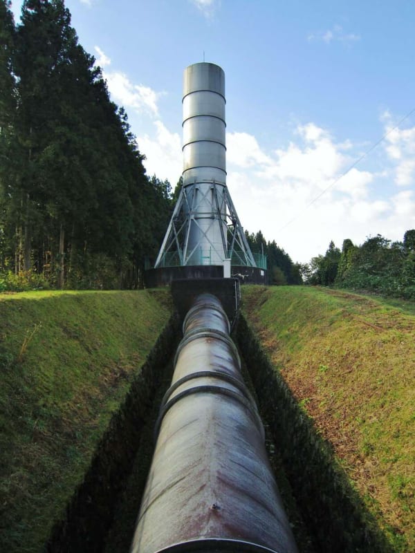
Is this the tank at thread1452-476852 and the subject is upgrading Surge Tank Anchorage at a hydroelectic plant for Seismic event ?
Thank God, and thank you so much for keeping us involved in this thread for tank anchors .
This snap from the above mentioned document;

ahardy_r9hlhs.jpg


...and IMO, self explanatory but find below my answers to your questions;
1. Is the intention that the equally space concentrated loads are applied at each anchor chair around the shell?
A= YES...

2. Is there a formula to calculate the maximum stress in circumferential direction? I know how to calculate the hoop stress using a uniform loading but not sure how to for concentrated loads. Would using Roarks formulas for rings be applicable?

A= There are some empirical formulas ( e.g. pressure vessel design manual) and structural engineering handbooks ( ring beam ).. You may use any structural engineering software also..
3. I assume I would need to add the hoop stress from hydrostatic load from inside the tank?

A= Hoop stress (due to hydrostatic load ) around the bottom diminishes and hard to solve.. you may add . How ever,in your case, the anchor forces are seismic and you may increase the allowable stress 30%.


Does this respond answers to your questions?

If not, pls come back to the original thread and reply the questions of tank people.

Good Luck..
 
Roark's has a load case for a circular beam loaded with N equally spaced radial loads that would be applicable.
I would assume that the ring itself and a portion of the shell above and below the ring act as the circular beam in this case. Hydrostatic load on that portion would also be additive to that. If necessary, the width of the ring could be increased, or a vertical flange added on the outside to increase area and section modulus. I think for wind girders, some of the codes use the 16t, some use 0.78(Dt)^0.5 or something like that, check the current D100 to confirm.
I've never had to actually do this, so I don't have any feel for how reasonable the numbers will work out.
In the past, I've checked regular anchor chairs up to 24" high or so, and with spacing about 3 times the top plate width, with top plate width up to 12" or so- but I'm not aware of any specific limits on those numbers.
 
Increasing the chair height is very effective in addition to increasing the number of the anchor bolts.
 
Thank HTURKAK - I apologize with other thread as I got side tracked with some other things and I meant to get back to it. It has been a rough few moments and this just came back up.

I appreciate your response and yes you answered my questions. I read the AISI document to be pretty straight forward but just wanted to make sure I was not missing anything. I wanted to make sure I interpreted correctly. I used the Roark load case for a circular beam and the stresses are very low compared to using individual chairs. I wanted to make sure I was not missing anything although in my head the continuous ring makes sense to drastically lower the localized stresses in the shell.
 

JStephen - That is exactly what I was looking at (Roark's circular beam with equally spaced concentrated loads). I get much lower stresses using the continuous top plate. To double check my hand calcs with software (I have Staad Pro), would it make sense to model a curved beam (half circle) and apply boundary conditions at the ends? I would model a full ring but applying the boundary conditions could mess with the results.


saplanti - I am getting 6-7 ft high chair which appears to be approaching the realm of "excessive". From what I have reviewed, most chair heights are in 12-24" range but they are also seeing much less load. Increasing the number of bolts would help but I already did increase the number and was told to try to limit the number.

 
Regarding the quantity of anchors, are you already in compliance with AWWA D-100 maximum spacing? Just curious, this tank must be quite a bit taller than it is wide? 130 kips is a pretty high per anchor load. Most of the tall and narrow tanks I have seen do have a continuous ring and lots of anchor bolts. Can you reduce the excessive 6-7 foot chair height by using a double plate?
 
IFRs - Yes it is a tall narrow tank (more like a standpipe) with H/Dia ratio almost two. The number of proposed anchors have been increased to meet AWWA maximum spacing requirements. I was also thinking of potentially using a doubler plate or repad.
 
Another consideration is getting the foundation to withstand fewer larger anchor forces vs more smaller ones. If you are at max spacing, you may look at putting two anchors at each location, with a continuous top plate between them. The tank shell and foundation considerations may combine to make your solution evident.
 
Ahardy89,

I agree, the chair height should not be that much. So, I would suggest you check the horizontal load that is applied onto the tank. Something in your calculation is not reasonable, especially in loading.
 
saplanti - the load per anchor is high but that's probably a function of the seismic factors, foundation type and a tall thin tank with product inside.
 
That is the one I am questioning. There might be some mistakes within the calculation, perhaps the load combination, density, wind pressure, seismic load whatever. They need to be rechecked perhaps the units, I do not know. Otherwise the chair load should not be that big.

In case there is no change in the load, it is the time that the diameter should get larger and the height shorter.
 
Saplanti - I should have specified but the loads in the anchors are to resist the seismic overturning moment (govern over wind). I am confident in the calculations to determine the anchor load (following AWWA D100 Chapter 13). The results were combined b\per ASD load combinations including accounting for the vertical component. One of my colleagues ran a quick FEM model and got similar results. The high loads are a function of the high ground acceleration and tall thin tank as IFRs speculated.

 
I am not the checker/verifier or the designer. I do not know your position either on the job.

If you are the designer you need to change the design to reduce the loads on anchor bolts or chairs.

If you are the verifier you need to report with your finding.

What else you are expecting us to help you?
 
Saplanti - Sorry if that came off in the wrong way I was just clarifying the loads did not seem unreasonable given the circumstances (it’s not a normal tank configuration). We are exploring retrofit options for the anchorage. My original post I was asking about the use of a continuous ring plate instead of individual chairs to mitigate the stresses in the outer shell (which is recommended in AISI in situations where the chair height is excessive).

I appreciate y’all’s input.
 
Note that attaching a circumferantial ring above anchor does not change the anchor loading.
If it is available the stress distribution on the shell side becomes much better and eliminates stress concentration above and around anchors. You can see the benefit by performing FEA easily.
In case the retrofit requires in these area you are in a correct path.
 
ahardy89 ;

So far, just we know that , you have a steel surge chamber which needs seismic upgrade at high seismic zone with H/D aspect ratio of around two and you calculated the anchors load or chair attachment (130 kips) which is pretty high..

Apparently you are not eager to provide more info. to get the whole picture.. But i think we are free to guess the situation and speculate more for the case.

Let me guess, I suspect that you have calculated the anchor load using the formula Ps = 4MS/(N *Dac) - W′/N which the formula is based on the assumption of elastic distribution of seismic moment on brittle anchor bars ... If the anchor bars ductile ( this is a must ) , the load dist . will be ; Ps = 8MS/(3N *Dac) - W′/N .
I suspect also, the seismic moment calculation is based on max. upsurge water level rather than steady state level. The fluctuation of water that is , time of oscillation last some minutes and max level is experienced for some several seconds.

The following vidoe is useful to get the concept..


Let us assume that your calculation is excellent and you stuck the size of anchors, chairs etc.. Providing more stronger anchors is not only option .. You may think the butressing of surge tank with bracing. The concept shown below;

surge_tank_butress_IMG_4852_l82we9.jpg


Dear ahardy89 ; If i were in your shoes , my approach will be;

- Try to learn the operation of surge tank, time of oscillation, the scheme of gates and valves..
- Ask the services of an expert for SEISMIC RISK ASSESMENT REPORT may be from a scholar..
- Perform the analysis based on the findings of SEISMIC RISK ASSESMENT REPORT ,
- If come a cross, look for other options ( ductile design of anchors, bracing from a higher level, perform the calculations as per ASCE 7 , ...)

I would like to remind also, the operation of surge tank can be delayed during a seismic event ( just keeping the steady state operation during a seismic shake) . The motorized gates will serve this condition..

Always remember;
- If All You Have Is a Hammer, Everything Looks Like a Nail...
- Never Play Leapfrog with a Unicorn.... Murphy's Law

Good Luck..
 
Status
Not open for further replies.

Part and Inventory Search

Sponsor