Navigation
Install the app
How to install the app on iOS
Follow along with the video below to see how to install our site as a web app on your home screen.
Note: This feature may not be available in some browsers.
More options
Style variation
-
Congratulations cowski on being selected by the Eng-Tips community for having the most helpful posts in the forums last week. Way to Go!
You are using an out of date browser. It may not display this or other websites correctly.
You should upgrade or use an alternative browser.
You should upgrade or use an alternative browser.
Anchorage length for rebar in shear stress 1
- Thread starter JuliusR
- Start date
- Status
- Not open for further replies.
- Thread starter
- #4
-
1
- #6
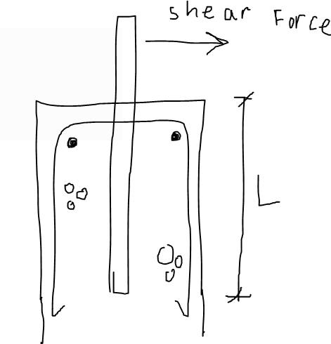
In ACI parlance, concrete anchorage as you've shown it here is a fairly involved evaluation process. This article will give you the flavor of it: Link. It will be difficult for anyone here to provide you with an "anchorage length" without first knowing a whack other parameters associated with your particular problem.
hardbutmild
Structural
- Aug 10, 2019
- 294
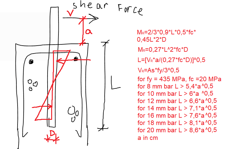
I'll try to do a quick and very rough estimation. To me it seems like there are two mechanisms of failure, shear failure of a bar and crushing of concrete due to rotation of a bar. I'd assume that the top and bottom 5% don't count into the part that'll transfer the load and I would assume linear stress in concrete. So the mechanism resisting a bending moment is shown in my picture. I assumed that the width is 2*D because I expect at least some area of surrounding concrete to help (this seems reasonable). If I want shear failure of a bar to happen before bending failure (I think this is better) I need at least the values shown on the right of my picture. I assumed some values that I thought made sense (at least to where I come from). All in all, it doesn't seem like it should go over the 60D that I usually use for classic tension bars. But then again... this is a very rough estimate.


hardbutmild said:...and I would assume linear stress in concrete.
That assumption -- effectively rigid bar behavior -- will turn out to be invalid, and unconservatively so, for anything even close to 60D embeddment. It might fly for something closer to 4D.
hardbutmild
Structural
- Aug 10, 2019
- 294
It's possible, depends on the length "a" I guess. Do you know of a document where something like that is discussed?
EDIT: sure, I agree that at 60D it's not valid, but when checking it seemed well below 60D, that's why I mentioned it. I assumed that the "a" is not really large so that might be another thing. I can see it being flexible, it certainly is. I just assumed that "a" is not very large (I always imagined it being up to a few inches). Also, I assumed that the bar yields, but I'd stress it to a lower level in reality. Now that I think about it, I don't think that I'd use anything below 20mm bar actually.
EDIT: sure, I agree that at 60D it's not valid, but when checking it seemed well below 60D, that's why I mentioned it. I assumed that the "a" is not really large so that might be another thing. I can see it being flexible, it certainly is. I just assumed that "a" is not very large (I always imagined it being up to a few inches). Also, I assumed that the bar yields, but I'd stress it to a lower level in reality. Now that I think about it, I don't think that I'd use anything below 20mm bar actually.
charliealphabravo
Structural
What are the relative loads and strengths and dimensions for the problem? The result can be highly dependent on the distance from the loaded edge of the concrete to the rod. If the loads are relatively low, then it is basically an Appendix D rupture cone problem for plain concrete with some credit given for the intersecting rebar. If the loads are high then you will need a strut and tie model to make it work and probably more reinforcement.
JuliusR - The "rod" sticking out of the top is a piece of rebar right? In that case wouldn't this just fall under ACI shear friction provisions which means you need to provide full development for the bar on each face of the joint, no reduction in development length allowed. This would kick back to few other discussions on here relative to Appendix D style checks for rebar anchorage.
Hardbutmild - take a look at TR 12 put out by the American Wood Council:
My Personal Open Source Structural Applications:
Open Source Structural GitHub Group:
Hardbutmild - take a look at TR 12 put out by the American Wood Council:
My Personal Open Source Structural Applications:
Open Source Structural GitHub Group:
hardbutmild
Structural
- Aug 10, 2019
- 294
Thanks, I'm aware of something similar for wood, but I assumed that if I used linear distribution of stress it would be safe (it'd give a larger required length). Guess I was wrong. I presume there are some differences in concrete and wood.Celt83 said:Hardbutmild - take a look at TR 12 put out by the American Wood Council:
hardbutmild said:It's possible, depends on the length "a" I guess. Do you know of a document where something like that is discussed?
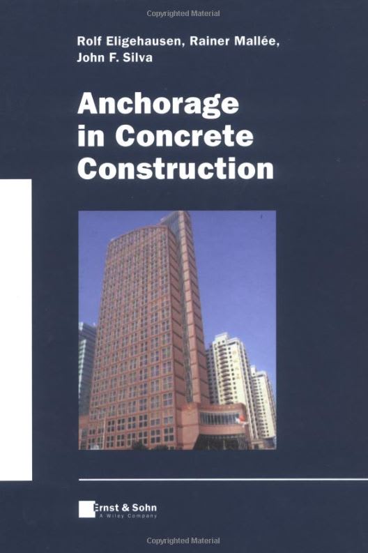
Sure. The current anchorage methodologies of most modern codes are based on the source material reproduced in the document below, authored by the leader in the field of anchorage to concrete.
hardbutmild said:I presume there are some differences in concrete and wood.
The situation for concrete is much worse than for wood because wood is a much softer material which tends to make the assumption of rigid anchor behavior more reasonable.
There was a time not so long ago when engineers felt pretty comfortable doing connection design on a first principles basis. Such designs have been proven to be faulty and dangerous in many instances including this anchorage stuff and the steel moment frame connection issues brought to light by the Northridge earthquake. I find this somewhat sad as I'm kind of a first principles sort of engineer. All one can reasonably do, though, is acknowledge the truth of things and move forward. As far as I'm concerned, most DIY connection designs are suspect until corroborated by testing. Structural engineers tend to excel at the large and come up short on the small.

- Status
- Not open for further replies.
Similar threads
- Locked
- Question
- Replies
- 5
- Views
- 4K
- Locked
- Question
- Replies
- 5
- Views
- 2K
- Question
- Replies
- 1
- Views
- 9K
- Replies
- 19
- Views
- 25K
- Question
- Replies
- 6
- Views
- 10K

