Eng-Tips is the largest engineering community on the Internet

Intelligent Work Forums for Engineering Professionals

Another Henry Smokey Yunick Hot Vapor Engine Thread 7

Status
Not open for further replies.
Mar 23, 2021
25
0
0
US
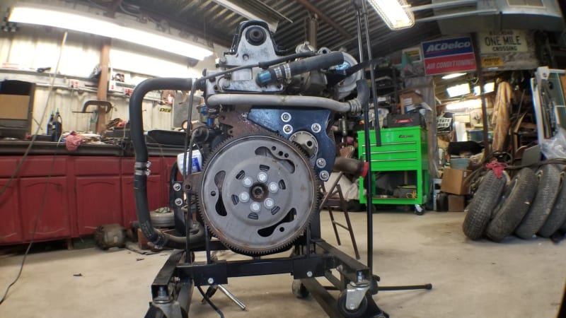
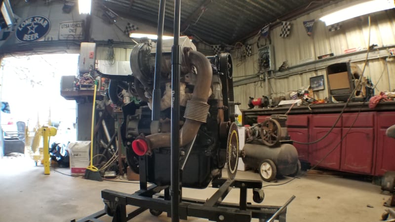
First, I am not an automotive engineer and I didn't spend the night at Holiday Inn. I jumped into this project only a few months ago and had a leg up because I know Danny Soliz very well and he is a life long adherent of Smokey, has studied the HVE and actually has 5 of the 10 known HVEs including the numbers matching Horizon and its engine. Overview: Running on a stand: Discussing cams for the Iron Duke version:
After having read what was readily available I have gone further down the research trail than most. I was aided by documents from DeLorean's files and other documents and articles from the past. What I have gleaned is that it is a polarizing issue driven by Smokey's legend, myth or infamous reputation. The claims are well know, but there is no proof. My question is this: Would the data pulled from 12 Dyno pulls and 10 road tests of MPG from SwRI be proof? How about reports by engineers at SwRI? Or reports and quotes from someone like Gregory Flynn who ran GM's Motor Division attesting to it working? If those showed approximately the 50MPG, Zero Emissions, 1.8 HP/CI from a 1.3l Engine using a carburetor and other tech available in 1982, would that be enough for people to say it worked?
 
Replies continue below

Recommended for you

@Greg: To be fair, that was 40 some odd years ago and carbureted. With current tech, who knows. As far as MPG is concerned, I have not been able to verify 50 or the 54 that I have seen in some places through actual tests or independent reports. What I can tell you is that I have seen the road tests that show 48.25. 133 Mile Loop of half city and half highway. 10 loops. Standard Drive-train "Slightly larger diameter, commonly available, tires were used in this test"
 
@Lou

I freely admitted at the start of the thread that I am not an Automotive Engineer. Underwater Acoustics, E-Commerce, Automotive Retail Video are more along the lines of my expertise. I came here looking for answers, specifically as to whether contemporaneous Dyno readouts and reports from engineers would constitute proof that the engine worked as advertised. So, I will pose the question to you. If, if you had access to tests results, such as the read outs from dyno pulls, could read the associated summaries from the testers (whose fiduciary duties were not to Smokey) and they showed that the engine did work, would that be proof enough for you.
 
No. I have no access to the engine or the test stand or any other test set-ups.

If it was a miracle engine, there are many companies that would have done the same research and duplicated the technique. The patent expired in 2003, lack of fee payment, so there is no legal protection for using the ideas.

This tells me that companies that make engines have seen this, read the claims, and walked away. That rarely happens for fundamentally good ideas.
 
Why not just build another engine identical to Smokey's and test it? It looks like it would be a fairly simple build and it would be interesting.
 
@BigClive: We are duel tracking. We are going to put the original 2.2 back in the 1981 Horizon and run it and modernize the Iron Duke and put it in an S10.
BD_81_Plymouth_ffdakn.png
1981_SY_Plymouth._k625gb.png
 
BigClive said:
Why not just build another engine identical to Smokey's and test it? It looks like it would be a fairly simple build and it would be interesting.

The tricky bit is duplicating the aspects that aren't documented anywhere. Some (ignition timing calibration, carburetor calibration, etc) requires instrumented testing of a known sample engine. Some of it, e.g. cam profiles and timing, can be sussed out by making careful measurements of an assembled engine with only minor disassembly. Some of it, e.g. port shapes and combustion chamber shapes, can be established to some extent by careful inspection and may require more intense disassembly.
 
We have five of them. Forensics are being performed on the test engine used for the failed kite version that was being contemplated with Crane. The problem with that one is that it is sort of a frankenstein version. For example the head had plenty of wear and the intakes valves showed the effects of high heat as would be expected, but the cylinders were brand new. The 2.2 that was in his daily driver is intact and has been run on the stand periodically over the years. The Chassis still has the dials as you can see in the picture and the half radiator that many believe to be mythical.
 
It's always good to have a thermodynamic theory explaining why it should work, as a road map for experimentation.

"Schiefgehen wird, was schiefgehen kann" - das Murphygesetz
 
From the point of view of the 1970s and early 1980s, when it was the norm to have air and fuel kinda-sorta-roughly mixed together in a carburetor and then unevenly distributed to cylinders through a common manifold whose walls were soaked with liquid fuel that had dropped out of suspension ...

... I can see the point of using the "homogenizer", a.k.a. a draw-through turbo. I can see the point of heating the manifold walls - but not so much the mixture contained within! - in order to vaporise any liquid that drops out of suspension and lands on a manifold wall.

I have a gut feel that the heated intake manifold wasn't actually heating up the bulk air-fuel mixture as much as was claimed, especially when the engine is running under load (high mass-flow-rate through the manifold). Air isn't a particularly wonderful heat-transfer medium. The surface area of the inside of the intake manifold is nowhere near as much as, let's say, the surface area of the finned surfaces of a modern turbo intercooler, for example. You may heat up the intake manifold walls to (let's say) engine coolant temperature, but that doesn't mean the intake charge is going to be reaching that temperature, or even coming close to it.

Thinking about this some more. At idle, and at part-load (light-load cruising), you WANT the engine to "not make power". The normal way of causing it to "not make power", i.e. draw in less air and fuel, is to throttle it (and run it at high intake vacuum). The pistons try to pull their normal volume in anyhow ... pumping losses. But another way to "not make power" is to heat up the charge. Then you make the charge take up more space, and run at lower intake vacuum ... lower pumping losses. So in this way, perhaps the amount of surface area available to the charge, had a wee bit of careful thought and experimentation put into it ... enough so that with low mass flow rate through the manifold (part-load operation and idling, which account for most of the operating time of most automotive engines) the charge gets heated up significantly, but at high flow rate, the intake charge doesn't spend enough time in contact with the hot manifold walls to heat up all that much. Doing the experiments to find that balance ... is what Smokey Yunick did. I wouldn't put it past him.

Nowadays, the way you cause an engine to "not make power" at part load, is to play with the intake cam timing in such a way that the intake stroke is intentionally less effective. It either doesn't draw a full charge in (early intake valve closure) or draws it in but pushes some of it back out again (late intake valve closure). And you respond to the driver's request at the accelerator pedal, by changing the cam timing. I have two different examples of how this is achieved sitting in my very own driveway. One engine is a Chrysler V6 Pentastar, which has variable valve timing that is separately adjustable on the intake and exhaust camshafts. The other one is a Fiat 1.4 MultiAir, which operates the intake valves hydraulically through a little solenoid valve that intentionally makes the cam lobe use less of its stroke at part load.

It would not surprise me one bit, to find out that Smokey's engines used conventional camshafts (single camshafts for all valves were standard practice back then) but with all event timings shifted later - achieving late intake valve closure, and simultaneously allowing the power stroke to be lengthened. The resulting impaired volumetric efficiency, he made up for with the turbocharger.

Nowadays, the way you avoid fuel maldistribution is to have a separate injector for each cylinder ... and as often as not nowadays, injecting directly into the cylinder.
 
I have a couple of engines in my fleet that were part of an emissions upgrade program. They're 2-stroke uniflow 71 series Detroit Diesel engines. The concept was to grind much of the lift off the exhaust cams and retard injection timing which simulated EGR and reduced NOx and PM emissions. A turbocharger was added to compensate for the loss of power. It's a good system and met US EPA Tier 2, Clean Cams Technology Systems was the outfit but it seems the company is defunct so we'll be replacing those engines this year as they've reached their 24k hour overhaul interval (with zero breakdowns).
 
@GregLoCock, I am sure we will at some point. Currently our Dyno is a CASREP victim of the thousand year winter event we had a few weeks back. Meanwhile, What's wrong with this for MPG:

"A mileage test for the vehicle was conducted using a 133 mile driving loop that included both city and highway speeds. The vehicle drive train, i.e., transmission, differential gearing, etc. was standard and unmodified. Slightly larger diameter, commonly available, tires were used in the test. With a final drive ratio of 2.3-1, the engine R.P.M. at 55 M.P.H. is 2,000. The vehicle speed was maintained within 2 mph of the posted speed limit. One hour and forty minutes of the test was spent in city traffic and an equal amount of time was spent in highway traffic. The 133 mile test loop was repeated 10 times and at the conclusion of the test it was found that the vehicle averaged 48.25 miles per gallon. The disclosed performance gains in both fuel economy and power output were obtained without sacrificing driveability.
It was also found that the engine was not prone to detonation even under high engine loads and low engine rpm. Moreover, the vehicle could be smoothly accelerated in high gear, from a road speed of 20 MPH, under both part and full throttle, without evidence of engine hesitation or flutter. The constant downshifting to maintain sufficient engine RPM often required with conventional, small displacement engines was found to be unnecessary."?
 
What's missing is the comparison to what the conventional engine would do under the same circumstances in the otherwise-same vehicle. (What vehicle was it?)

48 mpg US = around 5 litres per 100 km. That's pretty good, but not completely out of bounds for what many small cars of that era (and even now, if you can find one) will do with a normal engine under the hood if the driver has a light foot. Quote - "vehicle speed was maintained within 2 mph of the posted speed limit" - main reason my modern little car uses (somewhat) more than that, is that I don't drive like that!
 
US4592329-drawings-page-8_2_dnxv5c.png


An engine and fuel system embodying the present invention was constructed and installed in a 1980 Buick Skylark. The vehicle weighed 3,005 lbs, two passengers, full fuel accelerated 0-060 M.P.H. in 9.4 seconds. The mechanical parameters for the engine are listed in Table I. A measured torque curve is illustrated in FIG. 10 and indicates a remarkably level torque output, in excess of 225 ft-lbs, for an operating range of 2000-4400 rpm. Those in the art will recognize that the disclosed power output for a three-cylinder engine having a displacement of 125 cubic inches and weighing only 320 lbs. in its operating mode including clutch and bell housing is substantially more than one would expect from an engine this size. Moreover, it was found that the engine was remarkably vibration free and the radiator with which the above identified vehicle was originally equipped was reduced in size and capacity by about 50%.
TABLE I
Engine Type:3 cyl,overhead valve
Displacement: 125 cu.in.
Bore:3.950 in.
Stroke:3.4 in.
Rod length6.5 in.
Horsepower 240 Hp at 4000 RPM (special high performance fuel-test code 20 with 21 pound boost)
Horsepower 190 Hp at 4400 RPM (93 octane unleaded gasoline with 10 pound boost)
Weight 320 lbs.
Fuel economy 48.25 MPG (combined city and highway)


I have to convert those numbers to metric to make sense of them, but having done so ...

The torque curve above coincides with the claim of 190 hp at 4400 rpm, so from that, take the boost pressure to be 10 psi (0.7 bar gauge pressure, 1.7 bar absolute).

The BMEP based upon the claimed torque and RPM is around 19.3 bar.

For a forced-induction engine, at first approximation, divide this BMEP by the ratio of absolute pressure to atmospheric pressure (1.0 bar) to establish an estimate of what the BMEP would be in naturally aspirated form. It's 11.4 bar. This makes an implicit assumption of perfect intercooling.

By purposes of comparison, a run-of-the-mill low performance 2 valve per cylinder production car engine is commonly 11 - 12 bar BMEP, a good production engine 13-ish, and the very best naturally-aspirated 4 stroke spark ignition racing engines that are running on gasoline (no exotic fuel chemistry) - we are talking Formula 1 or NASCAR here - are in the 15 bar range.

So, it's fair to say that whatever cam timing or intake-heating trickery was applied, was probably costing it about 10% - 15% in specific torque. That would coincide with an increase in absolute temperature of 10% - 15%, which is not far off the deficit that one would expect with that boost pressure by not using an intercooler.

One other small thing worthy of mention here. Provided that you can keep the contained volume of the intake manifold down (and there's no intercooler, so that's easier in this case), draw-through turbo designs have the advantage that they can keep the turbo compressor spinning faster under part-load conditions because the compressor is operating under vacuum (so there's less load on it) ... it doesn't have to wait as long to spin up when the driver opens the throttle.
 
Keep it coming. I would love to get a closer look at the intake manifold (on any of them).

My working theory is that the surface temperature of the intake manifold may have been in the claimed temperature range, but the temperature of the intake charge was nowhere close to that at full load, although closer to it at idle and light load.

The timing of the valve events is another thing of interest.
 
Status
Not open for further replies.
Back
Top